Lecture 8 - UART: Universal Asynchronous Read and Write
UART. Lesing av og skriving til serieporten. Forklaring av baudrate.
UART (Universal Asynchronous Receiver-Transmitter)
UART is one of the most fundamental and widely used forms of serial communication in embedded systems. But what is Serial communication?
You can think of it this way:
-
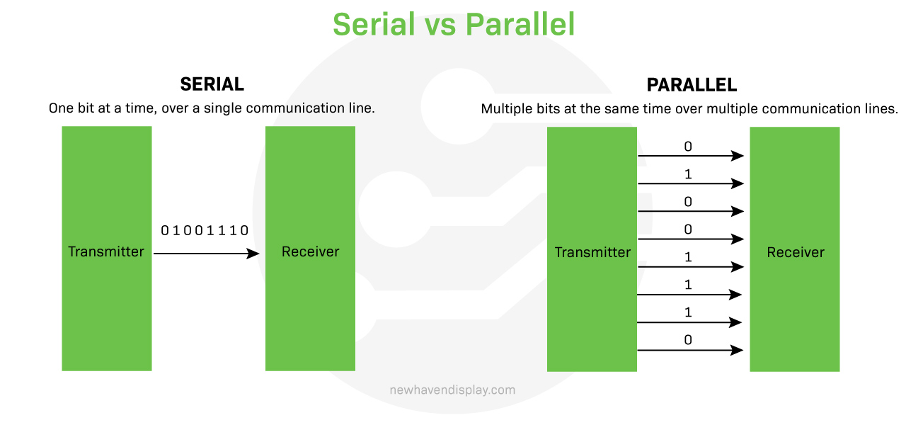
Parallel Communication is like moving 8 people across a room side-by-side (8 data lines). It’s fast, but takes a lot of space and works best over short distances.
-
Serial Communication (like UART) is like moving those 8 people in a single file line (1 data line). It’s slower, but requires much less space (only two wires: one to transmit, one to receive) and works reliably over longer distances.
 (Source: newhavendisplay.com)
Key Characteristics:
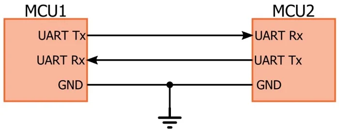
- Two Wires:
- TX (Transmit): Sends data.
- RX (Receive): Receives data.
- Full-Duplex: Can send and receive data simultaneously.
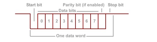
- Data Framing: Each data byte is wrapped with:
- Start Bit: Signals the receiver that data is coming.
- Data Bits (usually 8): The actual information.
- Parity Bit (optional): Used for simple error checking.
- Stop Bit(s): Signals the end of the data frame.
 (Source: allaboutcircuits.com)
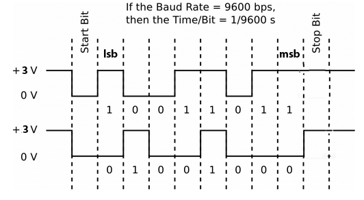
The “A” in UART, Asynchronous, is crucial: it means there is no shared clock signal between the transmitter and the receiver. Instead, the two devices must agree on the Baud Rate (the speed, or bits per second) and use special start and stop bits to synchronize their data streams.
The serial bits are shown below. It takes 10 bit-times to send 8 bits.
 (Source: people.ece.cornell.edu)
By knowing the Baud rate (for both transmitter and receiver), you don’t need a clock signal. You save one pin! Yayy! Both the transmitter and receiver knows that:
- To send one bit takes \(1/baudrate\) seconds
- As soon as the first low bit is received, the next 8 bits will be the actual data.
These are the rules of the UART. You may add some additional check-ups to ensure the data is not distorted on the way, such as adding parity, but it is not always needed.
What is parity?
A UART parity bit is an optional bit added to a UART data frame for simple error detection. It is set to a 0 or 1 to make the total number of ‘1’ bits in the data frame either even or odd, depending on the parity mode (even or odd). The receiving UART then checks if the parity of the received data matches the received parity bit; a mismatch indicates a potential transmission error, such as a single bit flip.
 (Source: docs.tibbo.com)
Let’s say you set Parity: Even and the data you want to send is integer 5. Then your dataframe in one package is 00000101 but your whole package is 0-00000101-1-1 as start bit + dataframe + parity + stop bit.
Let’s say you set Parity: Odd for the same scenario whole package is 0-00000101-0-1 as start bit + dataframe + parity + stop bit.
Let’s say you set Parity: Even and the data you want to send is integer 4. Then your dataframe in one package is 00000101 but your whole package is 0-00000100-0-1 as start bit + dataframe + parity + stop bit.
Let’s say you set Parity: Odd for the same scenario whole package is 0-00000100-1-1 as start bit + dataframe + parity + stop bit.
Note that the Word Lenght varies depending on your settings. The examples above are for Word Length = 9 including parity.
Does that make sense? Your parity bit ensures the set parity bool value that both transmitter and receiver agrees. If the set parity value and the parity of the whole package does not fit, then you know that your package is proken on the way due to long distance, improper media etc.
Exercise-1: Hello-world on terminal (finally!)
As we discussed before, a type of printing hello world to the screen is the fundamental first project when someone learns a new programming language. However, we have finished more than half of the semester without learning about how to print things on the screen. We have used a debugger, so we can somehow print the values of variables, but it is not an output of your system.
The reason why we waited so long is because printing things on the screen requires some level of understaning of these concepts:
- Sending data from your microcontroller to your PC
- Setting up the pins on your microcontroller to send the data
- Setting up some communication rules between the microcontroller and the PC
It is surely possible to give away all those settings step by step, and that you could print things on the screen without understanding the details much (as done here), but now it is time to learn those steps properly. In addition to learning how to “print” things on the screen, you will also understand how to make two microcontrollers transact data using serial communication on the same basis.
Let’s start with printing “hello world!” first:
- Create a new project without using the default mode.
- On the left, go to
System Core > RCC > HSE: Crystal/Ceramic Resonator. - On your Nucleo board,
USART3is typically mapped to the virtual COM port of the ST-LINK. This means when you plug the Nucleo board into your computer’s USB port, the ST-LINK bridge chip creates a Virtual COM Port (VCP) on your computer. Go to Pin Configuration setConnectivity > USART3 > Mode: Asynchronous. You will see thatPB10is set to TX andPB11set to RX. - However, these are not the pins that are hard-wired to our STLINK on our board. If you see in reference manual section 7.9, the STLINK actually uses
PD8andPD9.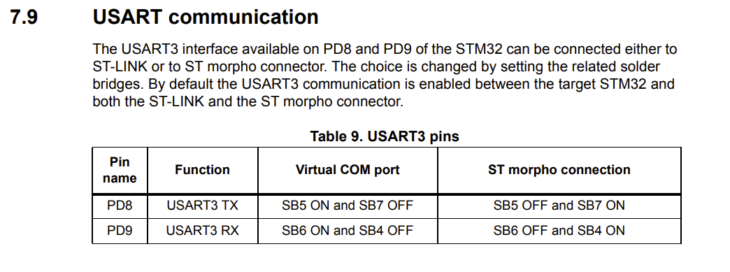 By holding CTRL, drag the
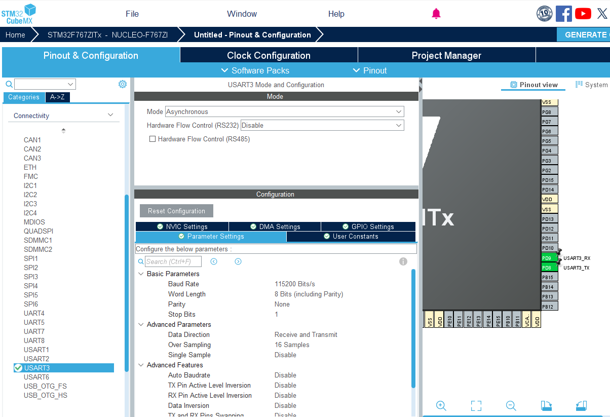
 PB10toPD8andPB11toPD9. - You don’t need to change anything at this step in USART3 configuration. Your final settings should look like this:
- Set your clock configurations as always with 8 MHz Input frequency, PLLCLK in system clock MUX, and HCLK 108 MHz. If you clock configuration is not correct, you will see either just gibberish or nothing at all on your terminal.
- Give a proper name and generate the code as usual: Basic application structure, STM32CubeIDE Toolchain, untick “Generate under root” and generate the code.
Now we are going to program the USART3 output in the code.
- First and foremost we need to create a
platformio.inifile before opening the project in PlatformIO. Now we need to pay attention that the monitor_speed must be the same as your Baud rate. Otherwise, again, you will see either just gibberish or nothing at all on your terminal.[env:nucleo_f767zi] platform = ststm32 board = nucleo_f767zi framework = stm32cube build_flags = -IInc upload_protocol = stlink debug_tool = stlink debug_build_flags = -O0 -g -ggdb monitor_speed = 115200 - Open the project in PlatformIO. Check
stm32f7xx_hal_msp.cthat your USART3 configurations are right:/**USART3 GPIO Configuration PD8 ------> USART3_TX PD9 ------> USART3_RX */ GPIO_InitStruct.Pin = GPIO_PIN_8|GPIO_PIN_9; GPIO_InitStruct.Mode = GPIO_MODE_AF_PP; GPIO_InitStruct.Pull = GPIO_NOPULL; GPIO_InitStruct.Speed = GPIO_SPEED_FREQ_VERY_HIGH; GPIO_InitStruct.Alternate = GPIO_AF7_USART3; HAL_GPIO_Init(GPIOD, &GPIO_InitStruct); - In the
main.cincludestring.hunder/* USER CODE BEGIN Includes */.#include <string.h> // Required for strlen() - Pay attention that a private variable, a handler, for our USART3 is created under
Private variables. This is the address we will work with to send and receive data via USART3.UART_HandleTypeDef huart3; - Under
/* USER CODE BEGIN 2 */define the message you want to send.// Define the message to send char *tx_data = "Hello world from HAL_UART_Transmit!\r\n"; uint16_t len = strlen(tx_data); uint32_t timeout = 100; // Timeout in milliseconds for blocking transmit - Transmit data via USART3 under
/* USER CODE BEGIN 3 */.HAL_UART_Transmit(&huart3, (uint8_t*)tx_data, len, timeout); HAL_Delay(1000); // Wait for 1 second for better visualization on terminal - Build and upload.
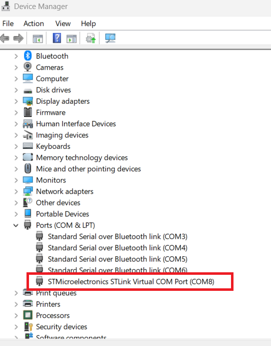
- Go to device manager and note the name of the COM port that your Nucleo is conneced. For me, it is COM8. And then, select it in PlatformIO.
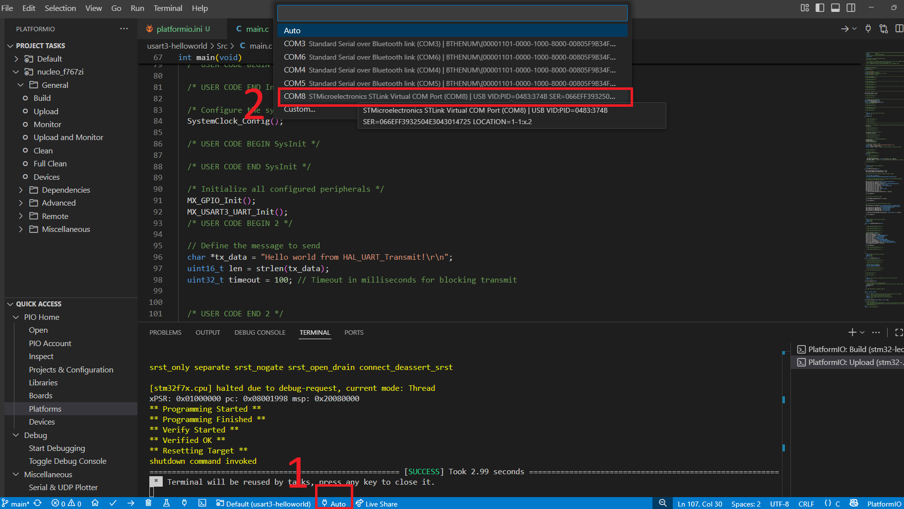
- After the upload, you should press the socket icon, or
Ctrl + Alt + Sto open serial monitor and see this output: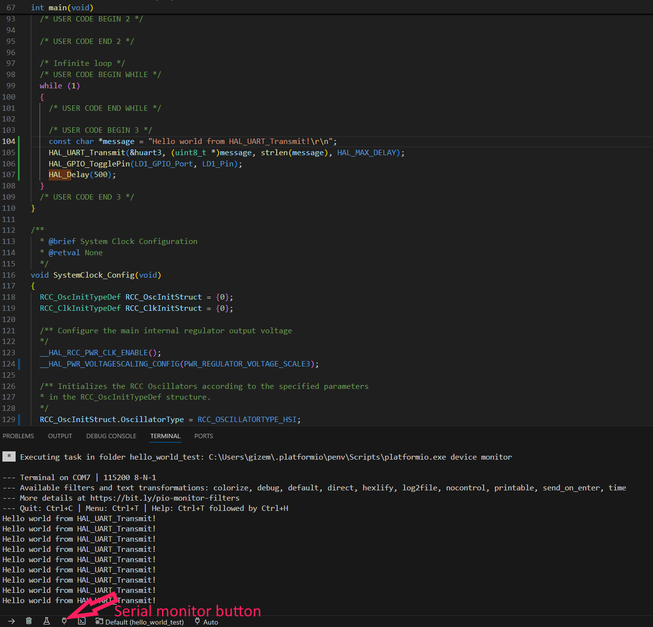 Also observe the Logic analyzer output:
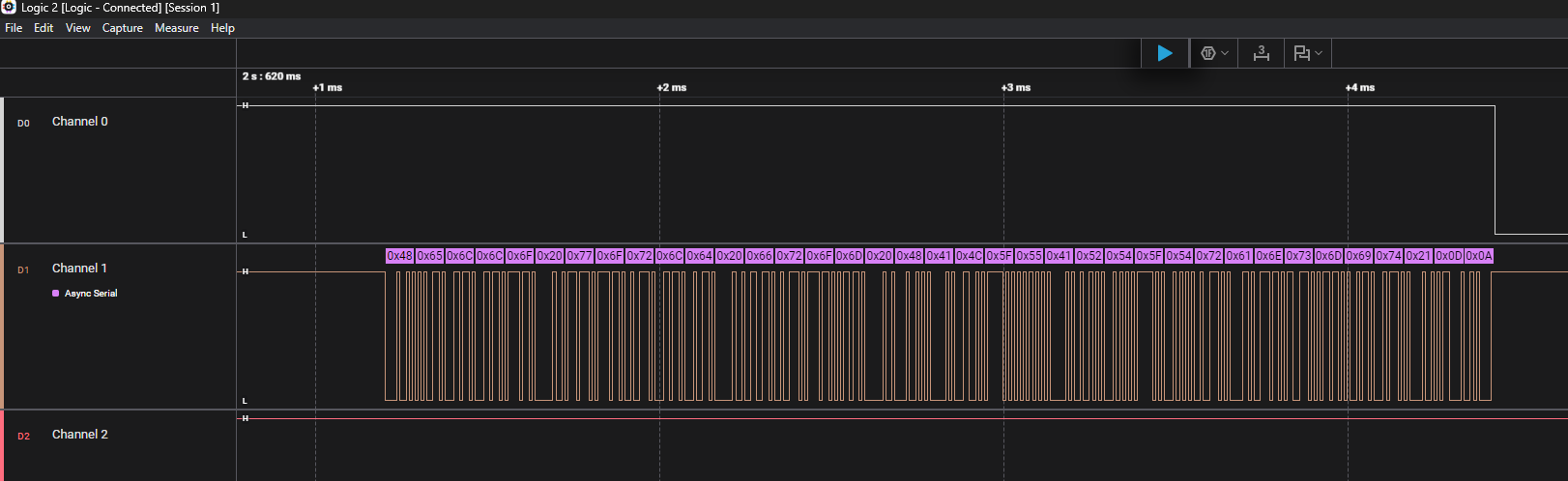
Note that at this point, you can use Putty as well to see your serial output.
With the given settings, how much does it take to send one package of data? (Hint: Word Length = 8, Baud rate = 115200)
Exercise-2: Sending ASCII or Byte
ASCII an acronym for American Standard Code for Information Interchange, is a character encoding standard for representing a particular set of 95 (English language focused) printable and 33 control characters – a total of 128 code points. When you send a string via UART, it will be encoded as ASCII.
So, if you change your text to, let’s say integer 5, you will not be seeing 0000 0101 as your dataframe.
- Under
/* USER CODE BEGIN 2 */change the message you want to send.// Define the message to send char *tx_data = "5"; // character 5 uint16_t len = strlen(tx_data); uint32_t timeout = 100; - Build, upload and observe on the oscilloscope - or a logic analyzer. The output will be like this:
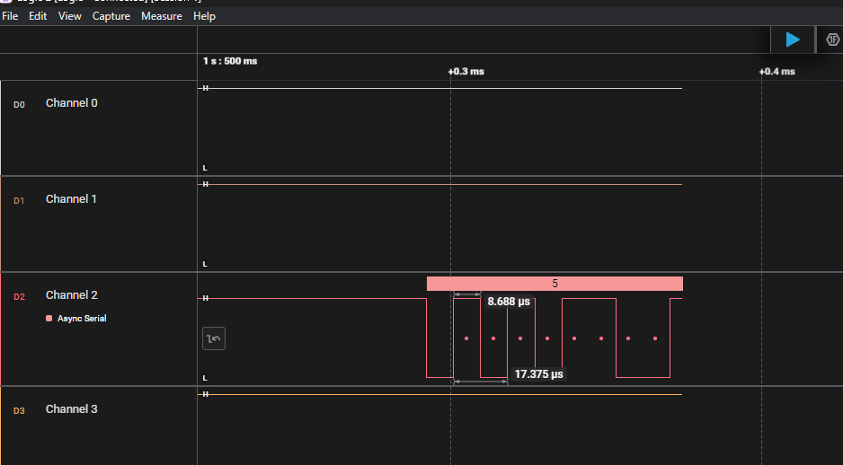 which my logic analyzer shows “5” on top, but if you pay attention to the bits, it is not 0000 0101.
 - However, if you send your data as Bytes like this:
  // Define the message to send
  uint8_t *tx_data = 5; // integer 5
  uint16_t len = 1; // 1 Byte
  uint32_t timeout = 100;
The output on the oscilloscope will be like this:
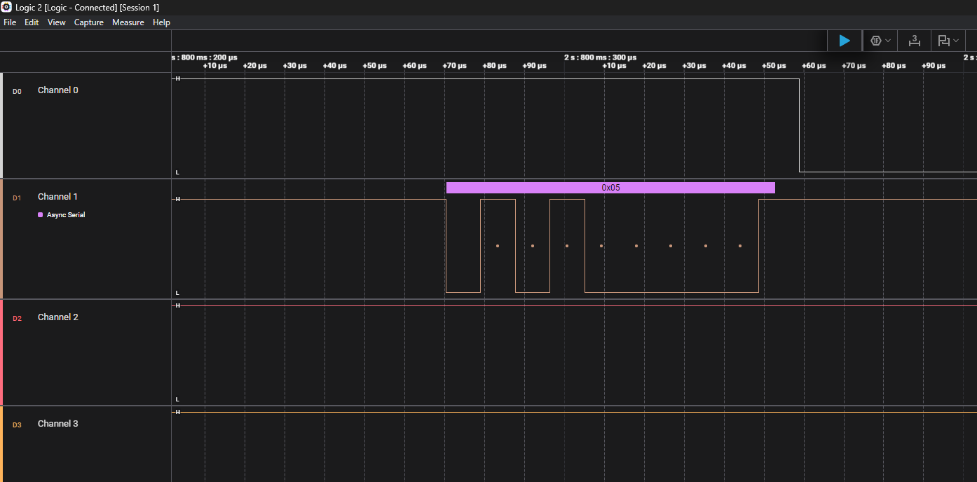 Note that you can change if it will be sent as 0000 0101 or 1010 0000 by changing the MSB First parameter in CubeMX.
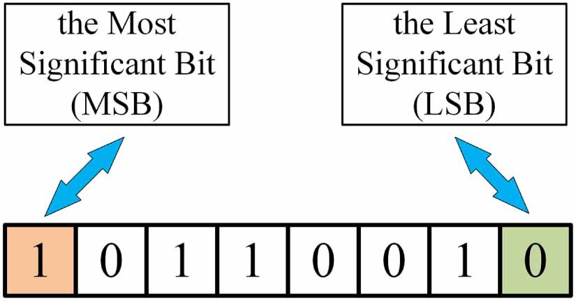
MSB (most significant bit) and LSB (least significant bit) refer to the bits with the highest and lowest value in a binary number, respectively. The MSB is the leftmost bit and has the greatest impact on the number’s value, while the LSB is the rightmost bit and has the smallest impact.
 (Source: researchgate.net)
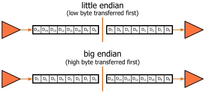
Little-endian and big-endian describe how multi-byte data (like a 32-bit integer) is stored in computer memory. In big-endian systems, the most significant byte (the “big end”) of the data is stored at the lowest memory address. In little-endian systems, the least significant byte (the “little end”) is stored at the lowest memory address.
 (Source: allaboutcircuits.com)
Alternatively sprintf
sprintf() is a standard C function used to format and store a string into a character array. It allows you to create formatted text (including numbers, variables, etc.) before sending it over UART or displaying it elsewhere.
You can use the same CubeMX configuration with the following code modifications:
- Generated the
main.cfrom your CubeMX with the same USART3 and clock configurations. - Add necessary includes after
/* USER CODE BEGIN Includes */:
  #include <string.h>
  #include <stdio.h>
- Place this after
/* USER CODE BEGIN 2 */:// Initialize an empty buffer with 100 free spots to fill later char transmit_buffer[100]; uint8_t timeout = 100; int tall = 50; - Send the data in the
while(1)loop after/* USER CODE BEGIN 3 */:// Prepare/Update the string we want to transmit through UART sprintf(transmit_buffer, "Sensorvalue : %d \n", tall); HAL_UART_Transmit(&huart3, (uint8_t*)transmit_buffer, strlen(transmit_buffer), timeout); HAL_Delay(1000); tall++;
If you have issues with sprintf(), you may want to update your platformio.ini to this:
[env:nucleo_f767zi]
platform = ststm32
board = nucleo_f767zi
framework = stm32cube
build_flags =
-IInc
-Wl,--undefined,_printf_float
upload_protocol = stlink
debug_tool = stlink
monitor_speed = 115200 ; Set the baud rate for the serial monitor
debug_build_flags = -O0 -g -ggdb
Exercise-2: Receive data from UART to toggle LED
Let’s change the direction of data transmission. In the previous exercise we received data from UART to our serial monitor. Now we will learn how to send data to our STM32F767 Nucleo board to control things connected to it. To make things simple, we will just control the built-in LD1 led for nw, but you know that you can control all other things such as motor speed, servo angle etc. using the same principle.
Now we will read a command (‘1’ or ‘0’) from the serial monitor and control the onboard green LED (LD1 on pin PB0).
- Create a new project targeting the STM32F767ZI without using the default mode.
- On the left, go to
System Core > RCC > HSE: Crystal/Ceramic Resonator. - Under “Pinout & Configuration,” go to
System Core > GPIO. - Select pin
PB0and set it to GPIO_Output and rename it toLD1. This is the pin connected to the green LED (LD1). - Under “Pinout & Configuration,” go to
Connectivity > USART3. - Set the Mode to Asynchronous.
- Change the default RX and TX pins to PD8 (TX) and PD9 (RX) since they are connected to our STLINK.
- In the Parameter Settings tab make sure the Baud Rate is set to 115200.
- In the NVIC Settings tab, check the box to Enable the USART3 global interrupt.
- Set your clock configurations as always with 8 MHz Input frequency, PLLCLK in system clock MUX, and HCLK 108 MHz. If you clock configuration is not correct, you will see either just gibberish or nothing at all on your terminal.
- Give a proper name and generate the code as usual: Basic application structure, STM32CubeIDE Toolchain, untick “Generate under root” and generate the code.
Now we can modify our code. At this step, it might be easier to use Putty or a Serial Monitor extension for VS Code.
- Copy the
platformio.inifrom your previous project. - Since we enabled interrupt for UART receive event, we want our variable to hold the received data to be global. Paste this in
/* USER CODE BEGIN PV */:#define RX_BUFFER_SIZE 1 uint8_t RxData[RX_BUFFER_SIZE]; - Now we can start the interrupt so that our callback will wait for a data to receive. Put this in
/* USER CODE BEGIN 2 */.HAL_UART_Receive_IT(&huart3, RxData, RX_BUFFER_SIZE); - As we discussed about weak functions that they are normally defined in their respective HAL library (i.e for UART the
__weak void HAL_UART_RxCpltCallback(UART_HandleTypeDef *huart)is defined instm32f7xx_hal_uart.c), and we don’t want to modify the CubeMX generated code, we will define anotherHAL_UART_RxCpltCallbackfunction in ourmain.c, but outside of the main() function. Paste this under/* USER CODE BEGIN 4 */.void HAL_UART_RxCpltCallback(UART_HandleTypeDef *huart) { // Check if the callback is for the correct UART peripheral if (huart->Instance == USART3) { // HAL_GPIO_TogglePin(LD1_GPIO_Port, LD1_Pin); // Debug this to check if you trigger RX interrupt if (RxData[0] == '1') { HAL_GPIO_WritePin(LD1_GPIO_Port, LD1_Pin, GPIO_PIN_SET); } else if (RxData[0] == '0') { HAL_GPIO_WritePin(LD1_GPIO_Port, LD1_Pin, GPIO_PIN_RESET); } // Restart the interrupt reception for the next character HAL_UART_Receive_IT(&huart3, RxData, RX_BUFFER_SIZE); } }
Open serial monitor, select the correct port. Make sure that there is no line ending in the data you send. Start the monitor and send 1 or 0 as text. Observe the LD1.
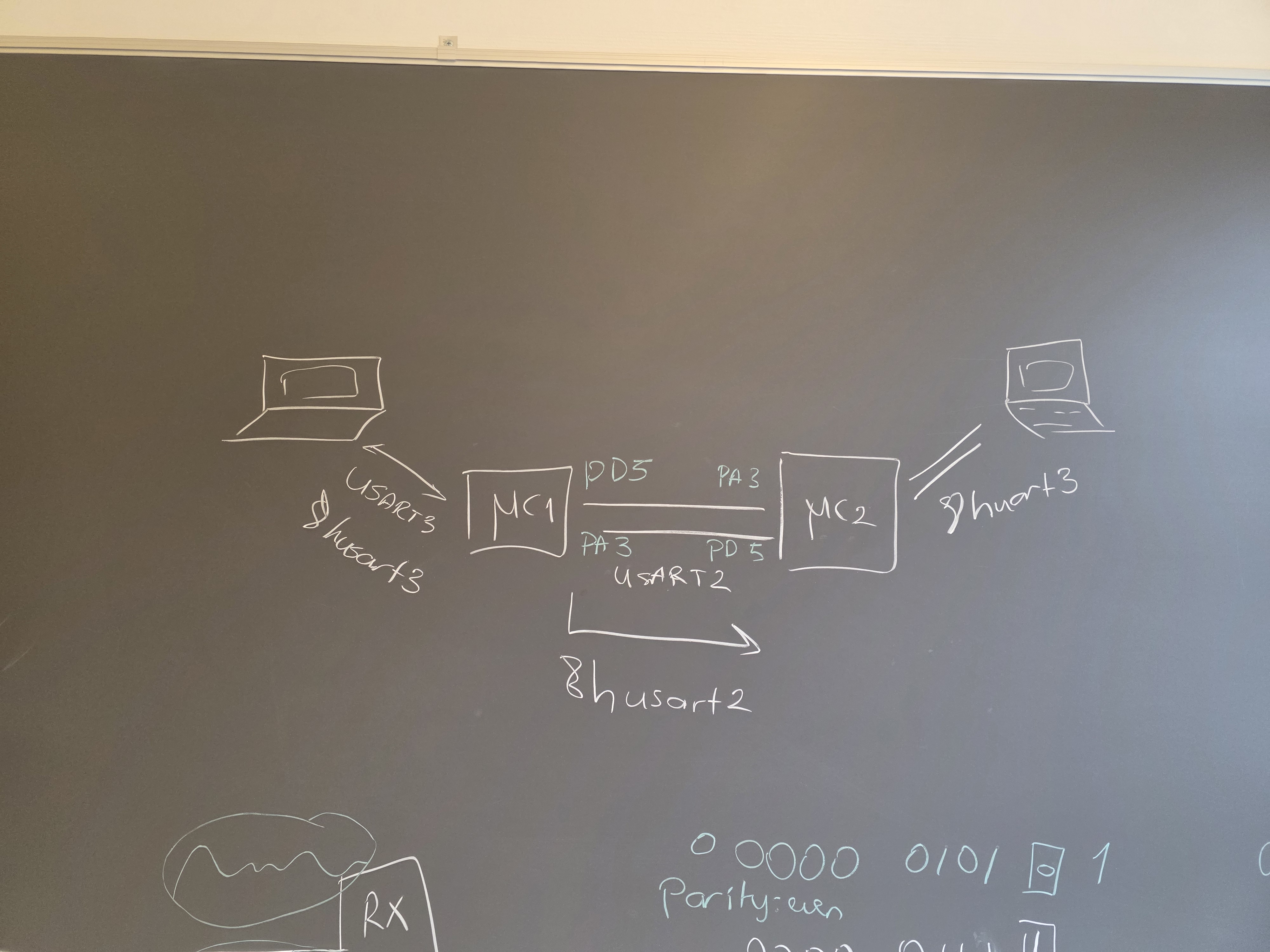
Exercise-3: Send data between two boards
As I mentioned before, since you have learned the basics of UART protocol, you can make two boards talk to each other! Find your best buddy and follow this tutorial together. This tutorial demonstrates how to establish one-way (simplex) Universal Asynchronous Receiver-Transmitter (UART) communication between two STM32F767ZI Nucleo boards. One of you wil be transmitter and the other will be receiver.
Configure the boards:
- Board 1 (Transmitter): Sends a simple text message periodically.
- Board 2 (Receiver): Listens for the message using interrupts and toggles an onboard LED when a message is successfully received.
DISCLAMER: I haven’t checked the tutorial below using two STM32F767 at the same time. Only debugged for each board through oscilloscope. Please let me know if you see any issues!
STM32CubeMX setup:
- Create a new project targeting the STM32F767ZI without using the default mode.
- On the left, go to System Core > RCC > HSE: Crystal/Ceramic Resonator.
- Set
PB0(pin connected to LD1) asGPIO_Outputand change its label toLD1. - Under “Pinout & Configuration,” go to Connectivity > USART3. This is the UART that will make the board communicate with its PC via serial monitor.
- Set the Mode to Asynchronous.
- In the Parameter Settings tab:
- Set the Baud Rate to 115200 (This is a common, reliable speed).
- Leave Word Length at 8 Bits, Parity at None, and Stop Bits at 1.
- Do the same for USART2 with pins
PD5andPA3. This is the UART that will make two boards communicate. - In the NVIC Settings tab, check the box to
Enablethe USART3 global interrupt. Note: While the Transmitter board doesn’t strictly need the interrupt, enabling it here ensures the configuration is identical for both projects. - Set your clock configurations as always with 8 MHz Input frequency, PLLCLK in system clock MUX, and HCLK 108 MHz. If you clock configuration is not correct, you will see either just gibberish or nothing at all on your terminal.
- Give a proper name and generate the code as usual: Basic application structure, STM32CubeIDE Toolchain, untick “Generate under root” and generate the code.
Hardware setup:
- Cross-Connect Data Lines: Connect the Transmit pin of Board 1 to the Receive pin of Board 2, and vice-versa.
- Board 1 (PD8/USART3_TX) → Board 2 (PD9/USART3_RX)
- Board 1 (PD9/USART3_RX) → Board 2 (PD8/USART3_TX)
- Common Ground: Crucially, connect the GND pins of both boards together.
Code implementation for Transmitter board:
- Copy
platformio.inifrom the previous project and open this one as PlatformIO project. - In
main.c, define the message and its length under/* USER CODE BEGIN PV */. Why not in/* USER CODE BEGIN 2 */? It could work in both places for Transmitter, but the Receiver uses interrupt. When we have ISR involved, we would like to define the private variables global, not local to main().char *TxData = "Hello from [NAME]\n"; // Change your name uint16_t TxSize = 13; // Length of the string including the newline - In the main
while(1)loop add the code to transmit the message under/* USER CODE BEGIN 3 */:HAL_UART_Transmit(&huart2, (uint8_t *)TxData, TxSize, HAL_MAX_DELAY); HAL_Delay(500); // Wait 500ms before sending the next message - Build and upload.
Code implementation for Receiver board:
- Copy
platformio.inifrom the previous project and open this one as PlatformIO project. - In
main.c, define the message and its length under/* USER CODE BEGIN PV */. Why not in/* USER CODE BEGIN 2 */? Because we enabled the NVIC for USART3. When we have ISR involved, we would like to define the private variables global, not local to main().#define RX_BUFFER_SIZE 13 uint8_t RxData[RX_BUFFER_SIZE]; - in the
main()function, add the following line under/* USER CODE BEGIN 2 */to start the interrupt-driven reception. This command initiates the UART to listen for data:HAL_UART_Receive_IT(&huart2, RxData, RX_BUFFER_SIZE); - Implement the UART Receive Complete Callback function outside of the
main()function. As we discussed in the interrupt lecture, those ISR callback functions are defined in the respectivestm32f7xx_hal_XXXX.cdrivers underDrivers\STM32F7xx_HAL_Driver\Src\. Since we enabled the NVIC for UART, our weak callback function is defined inDrivers\STM32F7xx_HAL_Driver\Src\stm32f7xx_hal_uart.c. So now, since we don’t want to overwrite any CubeMX generated code, we will re-define this in/* USER CODE BEGIN 4 */. This function is automatically called by the HAL when the expected amount of data (RX_BUFFER_SIZE) has been received.void HAL_UART_RxCpltCallback(UART_HandleTypeDef *huart) { // Check if the callback is for the correct UART peripheral if (huart->Instance == USART2) { // 1. Toggle the green onboard LED (LD1 on PB0) HAL_GPIO_TogglePin(LD1_GPIO_Port, LD1_Pin); // 2. Restart the interrupt reception for the next message HAL_UART_Receive_IT(&huart2, RxData, RX_BUFFER_SIZE); } } - Note that the
while(1)loop inmain.cis left empty for the Receiver, as all data handling is done in the interrupt callback. Although in embedded system it is better not to leave it “that” empty but put a smallHAL_Delay(100)to create a predictable “hang” behavior, ensuring the system stays active and responsive to its environment. -
However, if you want to see what transmitter sent on your Serial monitor, then you must add these:
 /* USER CODE BEGIN 2 */
 uint16_t len = 1; // 1 Byte
 uint32_t timeout = 100;
and
/* USER CODE BEGIN 3 */ HAL_UART_Transmit(&huart3, (uint8_t*)RxData, len, timeout); HAL_Delay(1000); // Wait for 1 second for better visualization on terminal - Build and upload
When Serial monitors are enabled:
Demonstration
- Ensure both boards are powered and correctly connected (Data lines crossed, GND connected).
- Once both boards are running, the green LED (LD1) on Board 2 (Receiver) should begin toggling every 500ms, confirming that it is successfully receiving the
Hello from [NAME]\nmessage being sent by Board 1 (Transmitter).
Can you discuss how to forward the received data to the terminal on the receiver board?
Bluetooth exercise
Pass it. Given as suggested project :)