Lecture 7 - DC motor drive and H-bridge
DC motordrift. H-bridge
Motor Drives
In general a motor drive is a power electronic device used to control the power delivered to a motor. The purpose could be either torque, speed or position control of the rotating motor shaft. At a high level the motor drive consists of a controller, and an amplifier (power electronics) which amplify the output from the controller to levels sufficient to drive the motor.
There are many different types of motors in existence, and each type warrants its own particular motor drive design. Unless the controller is very simple, microcontrollers are typically used for the controller, and the power electronics will be selected depending on type and size of the motor.
DC Motors: This is a very common motor in cheap low power applications. We can see it in remote control cars, robots, etc. This motor has a simple structure. It will start rolling by applying proper voltage to its terminals and change it’s rotational direction by switching voltage polarity. The DC motor torque (and thus speed) is directly controlled by the applied current. Current depends on voltage, and thus a voltage level less than the maximum tolerable voltage, will cause a speed that is less than maximum speed. By varying the applied voltage we will in practice wary the speed of the motor.
Stepper Motors: In some projects such as 3D printers, scanners and CNC machines we need to know motor spin steps accurately. In these cases, we may use stepper motors. Stepper motor are electric motors that divides a full rotation into a number of equal steps. The amount of rotation per step is determined by the motor structure. These kind of motors may be designed to have a very high accuracy if needed.
Servo Motors: There are many different types of motors that could be considered as servo motors. What they have in common it that they typically provide position control service. By using a servo you will be able to control the amount of shafts rotation and move it to a specific position. They usually have a small dimension and are the best choice for applications such as robotic arms.
AC motors Three phase AC motors are by far the largest consumer of electrical energy in the world. There are many different varieties of AC motors, but the type known as the induction motor serves a particularly important role in industry. This type of motor is typically used in applications where accuracy is less important, and for a very wide range of power levels from watts to megawatts. Examples include the driving of pumps, fans, drums, batching plants etc.
It is typically not possible to connect motors to microcontrollers or controller board such as Arduino or Nucleo directly. Unless the motor is really small it will require more current than the controller is able to supply. TheNucleo-144 has a maximum drive capability of 25 mA on each pin. Thus we need some form of circuit to amplify the signal from the controller, this kind of circuit is called motor driver, or motor drive. The driver is an interface circuit between the motor and controlling unit to facilitate driving.
In this lecture we will look at DC-motor drives. The understanding of DC-motor drives is a good foundation for understanding more advanced AC-motor drives, which are more used in big industries.
Introduction to DC motors
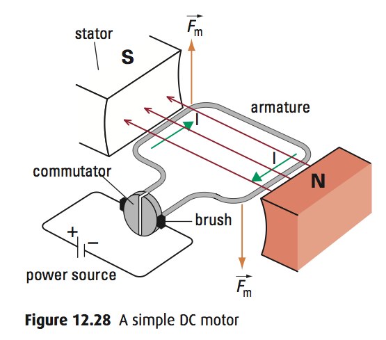
An electric motor is a device that converts electrical energy to mechanical energy with the help of magnets.
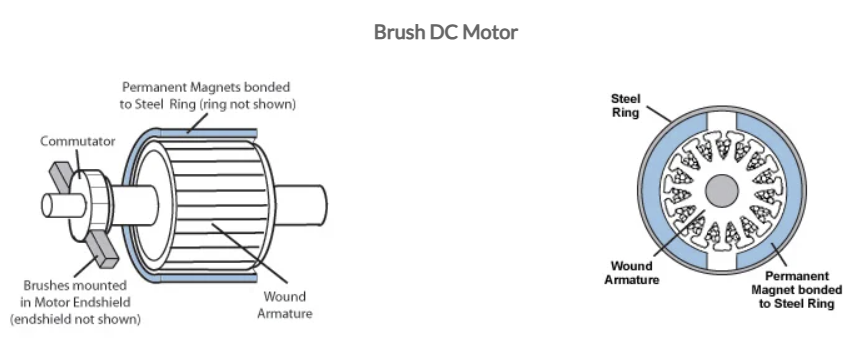
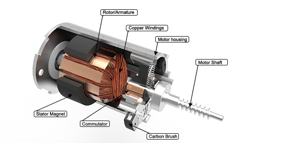
DC motors are divided into 2 main categories: brushed and brushless DC motors. We can define a brushed DC motor as a motor with internal mechanical commutation. It is designed to be powered by a direct current source. On the other hand, in the brushless DC motors, there is no physical contact between coils and the field magnet (stationary and rotaty parts). The brushless DC motor is really an AC motor with a electronic DC to AC converter placed inside the motor housing.
 (Source:orientalmotor.com)
How does brushed DC motors work? Watch this.
A brushless DC motor uses a permanent magnet as its external rotor and there are three phases of coils surrounding it. A specialized sensor is also typically placed in the setup to track the position of the rotor as it is moving, where the rotor position signals are being sent to a controller. A term often used for these devices is ESC (electronic speed controller). The ESC regulates the motor speed in order to track some reference speed, and can also provide dynamic braking where the rotational energy of the motor is converted back to electrical energy.
 (Source:orientalmotor.com)
How does brushless DC motors work? Watch this.
Brushed DC motors have been in commercial use since 1886. Brushless motors, on the other hand, did not become commercially viable until 1962. Brushed DC motors develop a maximum torque when stationary, linearly decreasing as velocity increases. Some limitations of brushed motors can be overcome by brushless motors; they include higher efficiency and a lower susceptibility to mechanical wear. These benefits come at the cost of potentially less rugged, more complex, and more expensive control electronics.
 (Source:itectec.com)
 (Source:motioncontrolonline.org)
 (Source:timotion.com)
DC motor control
The idea behind DC motor control is to connect a power source between two pins of the DC motor, and it will just work. However, we want to control it. We want to automatically turn it on and off via our microcontroller. Since we don’t have enough power to generate, we need to set a small circuit. We can use a simple transistor, MOSFET or a relay.
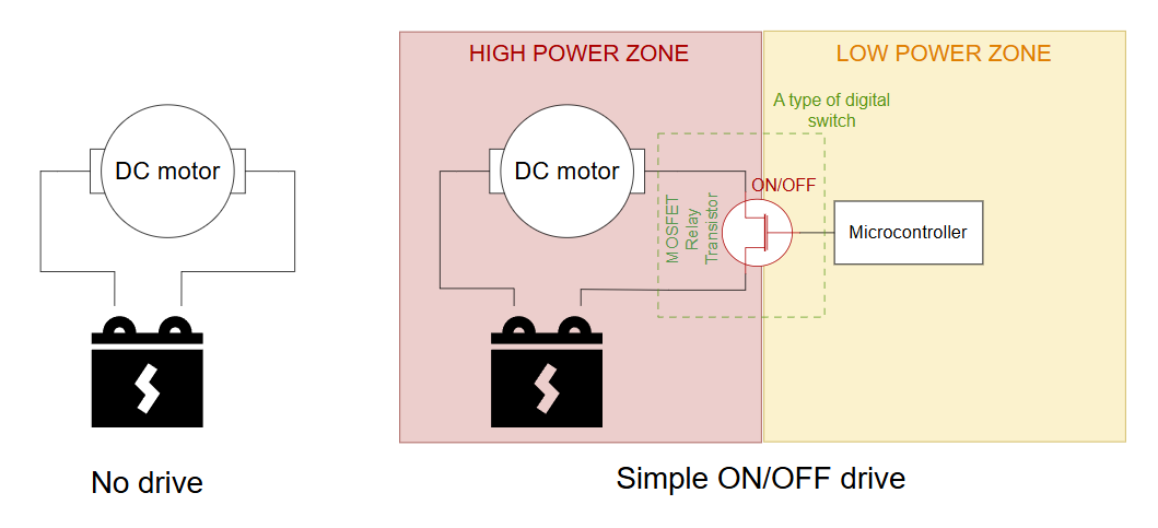
As we set our difital switch on and off, we can make the motor rotate or stop.
Can we change its speed?
 (Source: youtube/StuffBuilder)
However our microcontroller is done in this scenario and everything became manual. Another thing missing is that what if we want to change the direction of the motor as well as the speed automatically?
LM293D H-Brigde
An H bridge is an electronic circuit that switches the polarity of a voltage applied to a load. These circuits are often used in robotics and other applications to allow DC motors to run forwards or backwards.
This section provides a basic overview of the LM293D driver. More details about are available in the datasheet
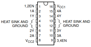
The L293D is a quadruple high-current half-H driver. The D in the name signifies that this version incorporates diodes on the outputs. It has a maximum output current of 600 mA, a maximum switching frequency of 5 kHz, and supports a voltage range from 4.5 to 36 V.
Depending on the degree of control that your application requires there are several possible ways to connect the motor.
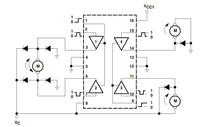
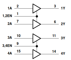
The following tables provides an overview of the possible control signal inputs, and the effect they will have in a DC motor drive application.


EN pin as shown H or L here, but it is the pin we will provide PWM signal. 1A and 2A are only for deciding the direction.
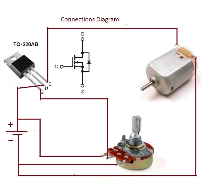
Exercise-1: Simple DC motor drive with L293D
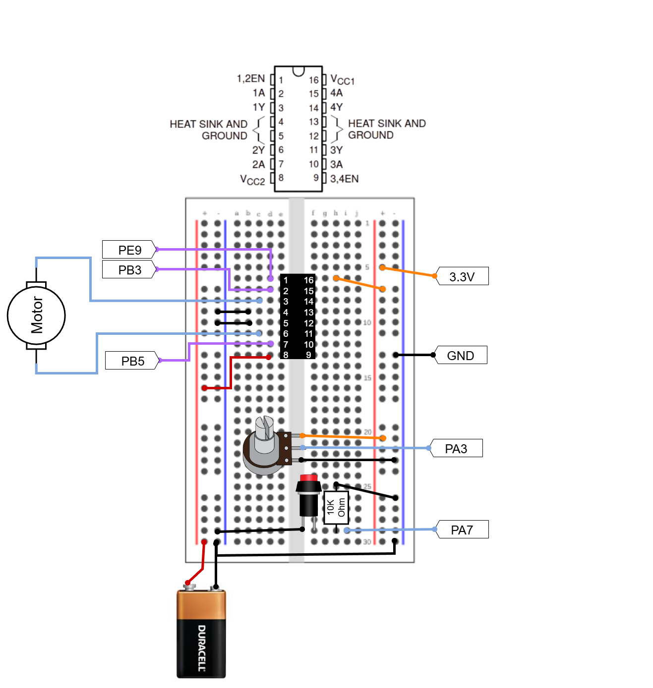
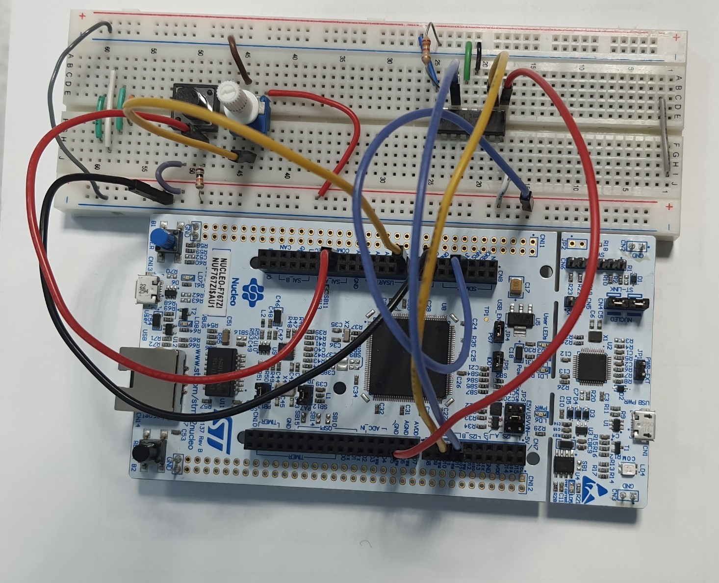
Hardware setup:
Set up this circuit. We will not use the potentiometer and the button in this exercise, but we will use them in the next ones.
PLEASE DO NOT CONNECT ANYTHING IF YOU ARE CONNECED TO YOUR PC VIA USB! First, unplug the USB power. Second, set up your whole circuit, including your 9V battery. Observe that the power LED of Nucleo is not blinking red (it means that there is a short circuit or power imbalance like if you connect your 3.3V and 9V on the same bus). Touch your L293D and check that it is not burning hot. Now, probably you can connect USB.
STM32CubeMX setup:
- Create a new project for the STM32F767ZITx (or select the NUCLEO-F767ZI board).
- On the left, go to
System Core > RCC > HSE: Crystal/Ceramic Resonator. - Configure GPIO for Direction Control:
- Locate and configure pin
PB3asGPIO_Outputand label it as IN_1A. (This connects to L293D 1A). - Locate and configure pin
PB5asGPIO_Outputand label it as IN_2A. (This connects to L293D 2A).
- Locate and configure pin
- Configure PWM for Speed Control (Enable Pin). We will use
TIM1:- Set your clock configurations as usual.
- Set TIM1 Clock Source to
Internal Clock. - Set Channel 1 Mode to
PWM Generation CH1. This will setPE9as PWM output. Change the label to ENA - Set the Prescaler to
108-1and the Counter Period (ARR) to999. Note that TIM1 is on the APB2 bus, and and its clock will also be operating 108 MHz in this setup.
TIM1_CH1pin is automatically set toPE9. Note that you could change it by pressing CTRL, toPA8as well.- Set your clock configurations as always with 8 MHz Input frequency, PLLCLK in system clock MUX, and HCLK 108 MHz.
- Give a proper name and generate the code as usual: Basic application structure, STM32CubeIDE Toolchain, untick “Generate under root” and generate the code.
Code implementation
- Create a
platformio.inifile with this content.[env:nucleo_f767zi] platform = ststm32 board = nucleo_f767zi framework = stm32cube build_flags = -IInc upload_protocol = stlink debug_tool = stlink debug_build_flags = -O0 -g -ggdb monitor_speed = 115200 - Open the project in PlatformIO. In the
main.cadd definitions for motor control state under/* USER CODE BEGIN PV */:uint32_t motor_speed = 0; // 0 to 999 (Counter Period value) - Add the following line to start the PWM signal under
/* USER CODE BEGIN 2 */:HAL_TIM_PWM_Start(&htim1, TIM_CHANNEL_1); // Note that htim1 is the handle generated by CubeMX for TIM1 - Time to implement the motor control logic.
- Rotate the motor in one direction slowly for 2 seconds
- Rotate the motor in one direction faster for 2 seconds
- Rotate the motor in the other direction slowly for 2 seconds
- Rotate the motor in the other direction faster for 2 seconds
- Stop the motor for 2 seconds
- Before paste-ing the code below, think about it. How you would implement this code?
Build and upload.
Unplug the GND pin of the battery to save some power unless you use it.
Some weird behaviours?
What happens if you press the RESET button on your board? If your motor runs even faster in one direction, then it is probably related to the raw hardware reset state of the GPIO pins. Why does it happen? When you hold the Reset button CPU is halted, which means the microcontroller’s CPU is stopped, meaning no code (main, MX_GPIO_Init, MX_TIM1_Init) is executing. All peripheral registers, including the GPIO Output Data Register (ODR), are reset to their default values. On many STM32 chips, the default hardware state of an unconfigured GPIO pin is either floating (which can be pulled HIGH by noise or capacitance) or weakly pulled HIGH for a short duration.
The L293D motor driver requires two conditions to run the motor:
- The Enable pin (your PWM pin) must be HIGH.
- One of the Input pins (
IN_1AorIN_2A) must be HIGH (the other LOW).
If the motor runs while you hold reset, it means the default hardware reset state of your pins is causing: (PWM Pin State=HIGH) AND ((IN_1A=HIGH) OR (IN_2A=HIGH))
Since you cannot control the hardware state while the chip is in reset, the fix is either:
- Hardware Fix (Most Robust): Add a physical pull-down resistor (e.g., 10kΩ) to the PWM Enable pin. If you want, you can also add 2 more 10kΩ to the Direction Pins (
IN_1A,IN_2A) on your circuit board. This guarantees the pins are held safely LOW (motor OFF) until the microcontroller’s C code starts running and configures them.
Software Fix (Defensive): Ensure that the pins that control the direction (IN_1A and IN_2A) are configured and forced to a safe, LOW state as the very first instruction set of the program.
Another issue might be that you experience something called classic transient state issue in microcontroller programming. If you observe a short moment that your motor spins fast, it is almost certainly due to a temporary full power signal (100% duty cycle) being applied to your L293D motor driver right as the peripherals stabilize.
Exercise-2: Adjusting DC motor speed with potentiometer
We will use the same circuit and almost the same CubeMX settings.
- Let’s try something new this time. Do not create a new CubeMX project, but go to your folders and find the previous project.
- Copy paste the whole folder and rename it to something make sense, f.ex
motor_drive_with_potentiometer. Rename both the folder and the CubeMX .ioc file in it. - Go to VSCode and open the project in PlatformIO. In this way, we don’t need to generate
platformio.inifile. It is already copied with the previous one. - Now, you can also open this project on CubeMX by just double clicking the .ioc file in the new folder.
- Configure GPIO for direction-change button: Locate and configure pin
PA7asGPIO_Outputand label it as DIR_BTN. By using this button, we will change the motor rotation direction: Stop->Clockwise->Counter-clockwise and go back to Clockwise. - Configure
PA3for potentiometer as analog input. Go toAnalog > ADC1 > Enable IN3. This will activatePA3asADC1_IN3. Re-label this pin asPOT_IN. By using this value, we will adjust the motor speed. Note that it would be much better to use ADC with DMA here, but in the tutorial, we will keep things simple. - Clock configuration, project name and settings are already inplace, just generate the code.
Code implementation
- There is already a bit of code from before. We will keep some of it.
- There are different ways of setting if-else statements but I think the most elegant solution for this exercise is to set up a finite state machine ❤️. Put this in
/* USER CODE BEGIN PTD */:// Define the states for the Motor Finite State Machine typedef enum { MOTOR_STATE_STOP = 0, // Explicitly set to 0 MOTOR_STATE_CW, // Defaults to 1 MOTOR_STATE_CCW // Defaults to 2 } MotorState_t; - Set some fix values as private definitions under
/* USER CODE BEGIN PD */:#define ADC_MAX_VALUE 4095 // Max value for 12-bit ADC #define PWM_MAX_VALUE 999 // TIM1 Period value (0 to 999 = 1000 counts) #define MIN_ACTIVE_SPEED 100 // Minimum PWM value to overcome motor friction (approx 10%) #define DEBOUNCE_TIME_MS 100 // Debounce time for button - Set some private variables and their initial values before we start under
/* USER CODE BEGIN PV */:uint32_t adc_value = 0; uint32_t current_pwm = 0; MotorState_t current_motor_state = MOTOR_STATE_STOP; // Initial state GPIO_PinState last_dir_btn_state = GPIO_PIN_RESET; uint32_t last_button_press_time = 0; - Time to update
/* USER CODE BEGIN 3 */. Read the ADC value, map it to between 0-999, and set it as PWM value in Additionally, read theDIR_BTNand toggle the motor rotation direction every press. Try yourself, before revealing the solution. My suggested code here get a bit long, since I implemented debouncing to the button, added a dead zone for the ADC-PWM mapping. Therefore, below there is link that will take you to the solution.
Click here if you want to see the solution
Build, upload and observe.