Lecture 6 - DAC and PWM
Skriving av analog verdi til utgang ved hjelp av DAC og PWM.
The Bridge from Digital to Analog
In the world of embedded systems, we often live in a digital realm of 1s and 0s. But the real world is analog—filled with continuous, changing values like sound, light, and temperature. A digital-to-analog converter (DAC) is the essential bridge that translates our discrete, digital numbers into these continuous, physical signals, most often a voltage. Think of it as a translator, taking a numerical command and turning it into a real-world action, like changing the brightness of an LED or controlling the speed of a motor.
While dedicated DACs are fantastic, they can be costly and aren’t always available on every microcontroller. For instance, many popular boards like the Arduino Uno or Mega 2560 don’t have a true DAC. So, what do we do? We get clever using the PWM “Trick”: Faking It Till You Make It 🤥
This is where Pulse Width Modulation (PWM) comes in. Instead of generating a single, continuous analog voltage, PWM generates a very fast-switching digital signal (i.e. a square wave that rapidly turns ON and OFF. By varying the duration of the “ON” time (the pulse width) relative to the total period, we can effectively control the average voltage output). A longer “ON” time results in a higher average voltage, while a shorter “ON” time results in a lower average. It’s not a true analog signal, but for many applications, it’s an excellent and cost-effective substitute like changing the brightness of an LED or controlling the speed of a motor.
The analogWrite() function on an Arduino is a perfect example of PWM in action.
Both true DAC conversion and PWM generation can be time-consuming processes for the CPU. If your microcontroller has to constantly manage these outputs, it can’t do much else. That’s where two powerful tools come into play: timers and Direct Memory Access (DMA). In this chapter, we’ll dive into how to use both real DACs and PWM, and we’ll learn how to use timers and DMA to make our systems run more efficiently.
Part 1: Regular DAC Operation
This guide shows you how to set up the STM32F767 Nucleo board to generate a basic analog output (Part-1) and a sine wave (Part-2) using the DAC.
Exercise-1: Basic DAC
- Create a new project without using the default mode.
- On the left, go to
System Core > RCC > HSE: Crystal/Ceramic Resonator. - Under “Pinout & Configuration,” go to Analog > DAC.
- Enable DAC_OUT1. This will automatically configure pin PA4.
- Leave the output buffer and trigger settings in their default states for this basic example.
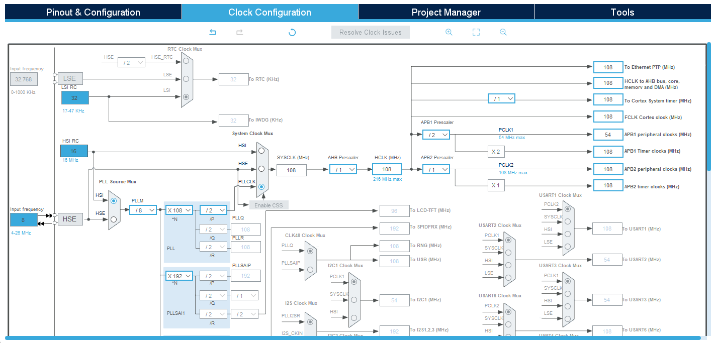
- Make sure the clock configurations look like this:
- Generate the code as usual.
Now we are going to program the DAC output in the code.
- Create a platformio.ini file with the content below and then open the folder as PlatformIO project as usual.
[env:nucleo_f767zi] platform = ststm32 board = nucleo_f767zi framework = stm32cube build_flags = -IInc upload_protocol = stlink debug_tool = stlink debug_build_flags = -O0 -g -ggdb monitor_speed = 115200 - Open
main.c. - Create a variable to represent the desired DAC output, for example:
uint16_t dac_value = 0;under/* USER CODE BEGIN PV */. - In the
main()function, add the following line to start the DAC under/* USER CODE BEGIN 2 */:HAL_DAC_Start(&hdac, DAC_CHANNEL_1); - Create a
forloop to increment the DAC output in the mainwhile(1)loop under/* USER CODE BEGIN 3 */. The digital value ranges from 0 to 4095.for(dac_value = 0; dac_value <= 4095; dac_value++) { HAL_DAC_SetValue(&hdac, DAC_CHANNEL_1, DAC_ALIGN_12B_R, dac_value); HAL_Delay(1); // Small delay to observe the change } - Compile and flash the code to the board.
Demonstration: Connect a voltmeter or oscilloscope to pin PA4 and observe the voltage sweep from 0V to 3.3V (or your VREF+ voltage).
You can also connect a LED (don’t forget a current limiting resistor apprx 100 Ohm), and observe its brightness changes.
Exercise-2: Sine Wave Generation with DMA
Let’s move on not only one step, but two steps at once. Now we will generate not a single analog value, but we will generate a sinusoidal output.
Additionally, this sinusoidal generation will be using DMA (as you have learned usage with ADC here) Remember, DMA (Direct Memory Access) allows peripherals like the DAC or ADC to transfer data directly to and from memory without CPU intervention, enabling faster and more efficient data handling in microcontrollers.
In this example our goal is to generate a 100 Hz sine wave using 100 samples. This will be important when we select the timer prescalar and modify main.c.
- Either create a new project without using the default mode, or modify your previous code.
- Follow the same RCC and Clock configuration settings as in the previous example.
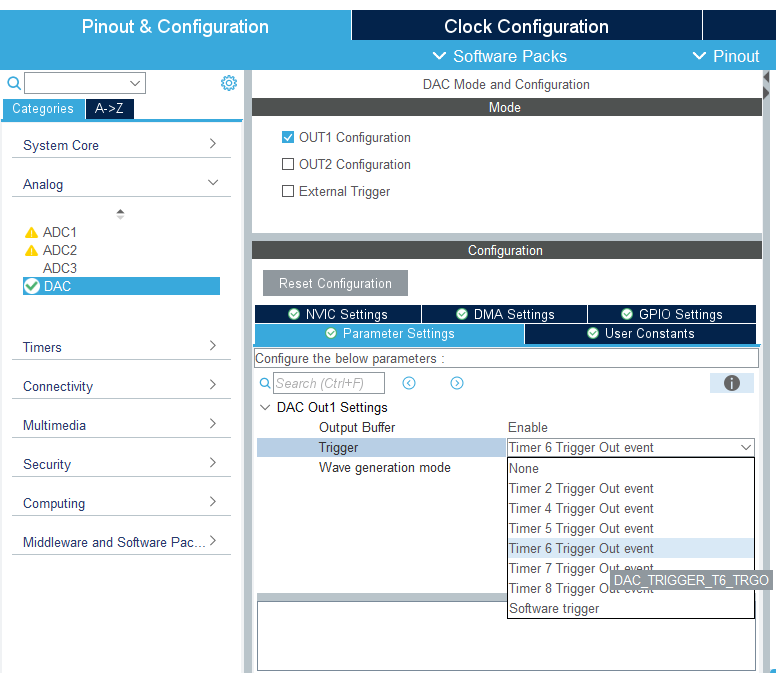
- Under “Pinout & Configuration,” go to Analog > DAC.
- Enable DAC_OUT1. This will automatically configure pin PA4.
- Set the trigger od DAC OUT1 to TIM6 Trigger Out.
- Under the DMA settings, add a new DMA request for DAC1.
- Set the Mode to
Circularand the Data Width toHalf Word. - Next, configure the timer. Navigate to Timers > TIM6.
- Set it Activated. Note that TIM6 is a basic timer that is hard-wired to use the internal APB1 clock as its sole clock source. The “Activated” checkbox is all you need to tick. By enabling the timer, you are implicitly selecting its internal clock.
- Under “Trigger Event Selection,” set the trigger to
Update Event. - Since our goal is to generate a 100 Hz sine wave using 100 samples, which requires a DAC trigger frequency of \(100\,\text{Hz} \times 100\,\text{samples} = 10{,}000\,\text{Hz}\) (or \(10\,\text{kHz}\)). the APB1 clock (which feeds TIM6) runs at 54 MHz. Therefore set your Prescaler to
54-1and the Counter Period (ARR) to99. This will achieve a 10 kHz DAC trigger frequency. - Generate the code.
Time to program the Sine Wave:
- Set up your PlatformIO project: Copy the platformio.ini from the previous exercise and open the project as PlatformIO project.
- Open
main.c. - Include the
math.hlibrary under/* USER CODE BEGIN Includes */. - Create a sine wave lookup table array to store the digital values under
/* USER CODE BEGIN PD */.#define M_PI 3.14159265358979323846 #define NUM_SAMPLES 100 uint16_t sine_wave_table[NUM_SAMPLES]; // could be better after USER CODE BEGIN PV - Create a
build_sine_wave()function after/* USER CODE BEGIN 0 */:void build_sine_wave(void) { for (int i = 0; i < NUM_SAMPLES; i++) { // Formula to convert a sine wave (-1 to 1) to a DAC value (0 to 4095) sine_wave_table[i] = (uint16_t)((sin(i * 2 * M_PI / NUM_SAMPLES) + 1.0) * 2047.5); } } - Start necessary things before the loop:
- Call the
build_sine_wave()function once in themain()function before thewhile(1)loop. - Start the DAC with DMA using the following function call:
HAL_DAC_Start_DMA(&hdac, DAC_CHANNEL_1, (uint32_t*)sine_wave_table, NUM_SAMPLES, DAC_ALIGN_12B_R); - Start the timer:
HAL_TIM_Base_Start(&htim6); - So the code under
/* USER CODE BEGIN 2 */looks like this:build_sine_wave(); HAL_DAC_Start_DMA(&hdac, DAC_CHANNEL_1, (uint32_t*)sine_wave_table, NUM_SAMPLES, DAC_ALIGN_12B_R); HAL_TIM_Base_Start(&htim6);
- Call the
- Build and upload (finally!).
Demonstration: Connect an oscilloscope to pin PA4. You should see a clean 100 Hz sine wave. You can modify the timer settings in CubeMX to change the frequency.
This is a nice video tutorial for those who likes videos better.
Part 2: Pulse Width Modulation (PWM)
What is Modulation?
What is a pulse?
We need to talk.
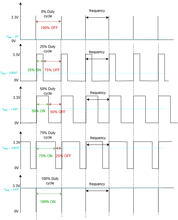
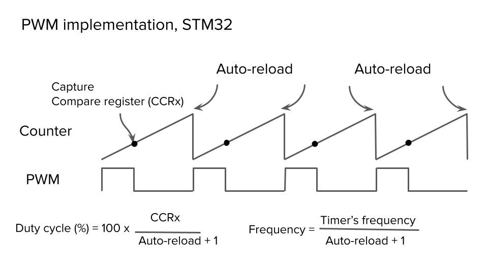
The picture shows how duty cycle would chage based on generated analog-ish output. There are two primary components that define a PWM signal’s behavior:
- Duty cycle: A duty cycle is the fraction of one period when a system or signal is active. We typically express a duty cycle as a ratio or percentage. A period is the time it takes for a signal to conclude a full ON-OFF cycle.
- Frequency: The rate at which something repeats or occurs over a particular period. In other words, the rate at which a vibration happens that creates a wave, e.g., sound, radio, or light waves, typically calculated per second.
In our board: Up to 16 PWMs available from the four full-featured general-purpose timers (TIM2, TIM3, TIM4, TIM5) alone, plus additional channels from other timers.
For more details check here.
Exercise-3: LED Dimmer with PWM
Let’s translate our DAC knowledge to the world of PWM to control the brightness of the blue LED (LD1). The principle is similar: we’re using a timer to generate a signal, but this time, the output is a fast-switching digital signal that mimics a changing analog value.
If you check the datasheet, you see that TIM1 and TIM8 are advanced-control timers and perfect for PWM output generations.
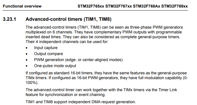
It is surely possible to use any of the general-purpose timers, but since out TIM1 is free right now, we can simply use the “good one” :D
- Create a new project without using the default mode.
- On the left, go to
System Core > RCC > HSE: Crystal/Ceramic Resonator. - Configure TIM1:
- Set your clock configurations as usual.
- Set TIM1 Clock Source to
Internal Clock. - Set Channel 1 Mode to
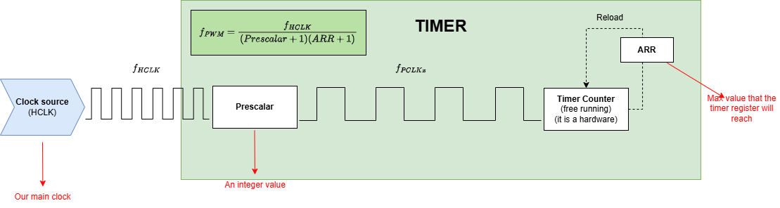
PWM Generation CH1. - Set the Prescaler to
108-1and the Counter Period (ARR) to999. Note that TIM1 is on the APB2 bus, and and its clock will also be operating 108 MHz in this setup.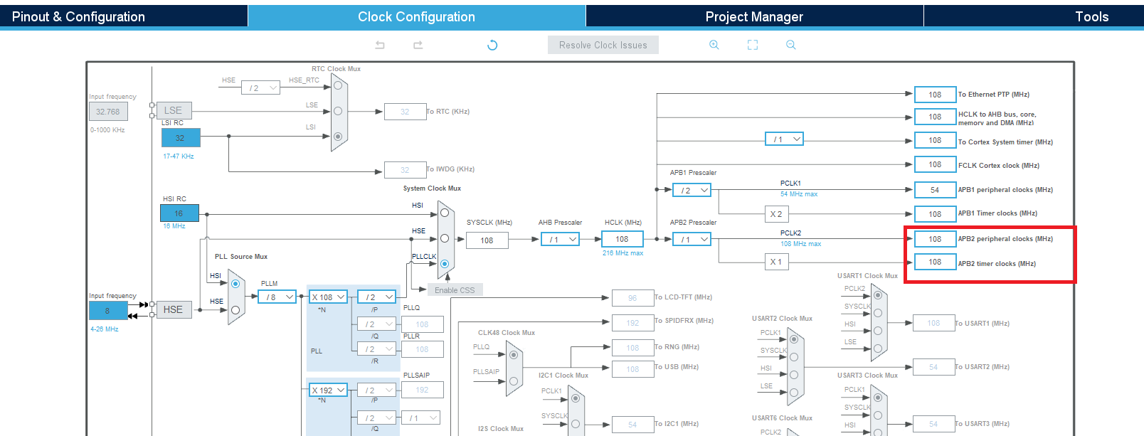 So, our timer’s new frequency becomes:
\(108 MHz/108=1 MHz\)
So, our timer’s new frequency becomes:
\(108 MHz/108=1 MHz\)
This gives us a nice, round base clock of 1 MHz to work with. It makes calculating the PWM period (with the
ARRregister) very easy. For example, if you set theARRto 999, you’ll get a perfect 1 kHz PWM signal, since \(1 MHz/(999+1)=1 kHz\). TIM1_CH1pin is automatically set toPE9. Note that you can change it by pressing CTRL, toPA8as well.- Generate the code and then open
main.cin your PlatformIO project. - Create a variable to represent the desired PWM duty cycle under
/* USER CODE BEGIN PV */.uint16_t pwm_value = 0; - In the
main()function, start the PWM signal generation under/* USER CODE BEGIN 2 */:HAL_TIM_PWM_Start(&htim1, TIM_CHANNEL_1); - In the main
while(1)loop, add the following code under/* USER CODE BEGIN 3 */to make the LED slowly fade up and down:// Fade up (increase brightness) for(pwm_value = 0; pwm_value <= 999; pwm_value++) { __HAL_TIM_SET_COMPARE(&htim1, TIM_CHANNEL_1, pwm_value); HAL_Delay(1); // Small delay to make the fade visible } // Fade down (decrease brightness) for(pwm_value = 999; pwm_value > 0; pwm_value--) { __HAL_TIM_SET_COMPARE(&htim1, TIM_CHANNEL_1, pwm_value); HAL_Delay(1); } - Build and upload.
Demonstration:
Observe the external LED on PE9. The brightness should smoothly increase and then decrease in a continuous loop.
I have observed some issues while preparing this exercise. Some are common embedded system issues, some are just weird and I am not sure why. I want to mention here so you can try to implement those debugging steps if you also experience similar problems:
1) HAL_Delay(1) was not 1ms in the for loop, but HAL_Delay(500) is 500ms outside the for loop. I just don’t know why. Therefore, my observation of the full-cycle of fade-up/down were taking 4 seconds whereas I’d expect it to take 2 seconds. Flashing the board a few times other codes helped and the code above works fine…
2) Replacing HAL_Delay(1) in the for loop with for(delay_counter = 0; delay_counter < 10000; delay_counter++); seems like solving the problem, but only after putting the code in debug mode once. Since the delay for loop is an empty loop, the compiler optimizes it out.
3) The best solution in this scenario to both of these issueswould be to use a hardware timer to control the fading. A timer is an independent hardware peripheral that is not affected by CPU cycles or compiler optimizations, making it the most accurate way to handle time-sensitive tasks.
Mapping signals with different dynamic range
Suppose your input signal has a range of 0 - 1023 considering that you are using 10-bit ADC, and you need to drive the PWM which expects a value of 0 - 999 considering that you set your timer’s ARR to 999 to generate PWM signal. The larger dynamic range input signal needs to be mapped to the lower dynamic range parameter of the PWM control signal.
pwm_pulse = (uint32_t)adc_value * PWM_PERIOD_VALUE / ADC_MAX_VALUE;
Or you may use the following generic equation, where x is the input, and y is the output signal.
\[y = \frac{(x - x_{min}) \cdot (y_{max} - y_{min})}{(x_{max} - x_{min})} + y_{min}\]For our example, this yields:
\[y = \frac{(x - 0) \cdot (999 - 0)}{(1023 - 0)} + 0 = x \cdot \frac{999}{1023}\]long map(long x, long in_min, long in_max, long out_min, long out_max)
{
return (x - in_min) * (out_max - out_min) / (in_max - in_min) + out_min;
}
Hence to map an analog input value, which ranges from 0 to 1023 to a PWM output signal, which ranges from 0 - 999, you can use the :code:map(value, 0, 1023, 0, 999) function. This function has five parameters, one is the variable in which the analog value is stored, while the others are 0, 1023, 0 and 999 respectively. Be careful! These values will be different based on how you set ADC and PWM configurations.
Exercise-4: Potentiometer and LED dimmer with PWM
- Create a new project without using the default mode.
- On the left, go to
System Core > RCC > HSE: Crystal/Ceramic Resonator. Set your clock configurations as usual. - Configure ADC:
- Navigate to
Analog > ADC1. EnableIN3onPA3. This connects the potentiometer’s wiper to the ADC channel. - Set the Resolution to
10-bit. - Under Parameter Settings, ensure the Continuous Conversion Mode is set to
Disableand the End of Conversion Selection is set toEOC flag at the end of single conversion. We are doing polling method for ADC, where the code polls for the result of a single ADC conversion.
- Navigate to
- Configure TIM1:
- Set your clock configurations as usual.
- Set TIM1 Clock Source to
Internal Clock. - Set Channel 1 Mode to
PWM Generation CH1. - Set the Prescaler to
108-1and the Counter Period (ARR) to999.
- Generate the code and then open
main.cin your PlatformIO project. - Create a some private definitions for constant values we set for this project under
/* USER CODE BEGIN PD */.#define ADC_MAX_VALUE 1023 // 10-bit ADC has a max value of 1023 #define PWM_PERIOD_VALUE 999 // TIM1 ARR is set to 999 - And some global variables under
/* USER CODE BEGIN PV */.uint16_t adc_value = 0; uint32_t pwm_pulse = 0; - Start the PWM after
/* USER CODE BEGIN 2 */:// Start the PWM on TIM1 Channel 1 HAL_TIM_PWM_Start(&htim1, TIM_CHANNEL_1); - Constantly read the ADC value from potentiometer, map it, and apply it as CCR value for PWM after
/* USER CODE BEGIN 3 */:// Start ADC conversion HAL_ADC_Start(&hadc1); // Poll for the end of conversion HAL_ADC_PollForConversion(&hadc1, HAL_MAX_DELAY); // Get the ADC value (0-1023) adc_value = HAL_ADC_GetValue(&hadc1); // Stop ADC conversion HAL_ADC_Stop(&hadc1); // Map the 10-bit ADC value (0-1023) to the PWM period (0-999) // Formula: output_value = (input_value * output_range) / input_range // In our case: pwm_pulse = (adc_value * 999) / 1023 pwm_pulse = (uint32_t)adc_value * PWM_PERIOD_VALUE / ADC_MAX_VALUE; // Set the new PWM duty cycle __HAL_TIM_SET_COMPARE(&htim1, TIM_CHANNEL_1, pwm_pulse); // Small delay for stability HAL_Delay(10);
Part 3: Servo motor control
Servo motors are so fundamental, especially in mini hobby projects and in small-robotics comunity. They provide precise angular movement between 0 and 180 degrees. Unlike standard DC motors, you don’t just turn them on or off; you tell them exactly what position to hold.
We will learn more about motor control in … but actually a servo motor is a simple DC motor with a bunch of gears and a feedback circuit. It does have an H-bridge (it will also come in DC motor control lecture). If you are curious, you can watch this youtube video about how servo motors work and what it is inside this blue/black box :)
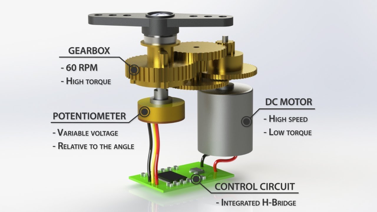 (Source:youtube.com/How To Mechatronics)
To control a servo motor, you need to generate a specific type of PWM signal:
- Fixed Frequency (Period): Servos require the control signal to repeat every 20 milliseconds, which translates to a frequency of 50 Hz. This is the timer’s total period (our ARR value).
- Variable Pulse Width (Duty Cycle): The angle is determined by the short high-time pulse within that 20 ms window:
- A pulse width of 0.5 ms typically corresponds to 0 degrees (minimum angle).
- A pulse width of 1.5 ms typically corresponds to 90 degrees (center).
- A pulse width of 2.5 ms typically corresponds to 180 degrees (maximum angle).
By precisely configuring our STM32 timer to hit this 50 Hz period and then manipulating the pulse width between 1ms and 2ms using the CCR (Capture/Compare Register), we gain full control over the servo’s position.
Exercise-5: Simple servo motor angle set
In this exercise, you will learn how to set up a 50 Hz PWM signal to control a standard hobby servo motor.
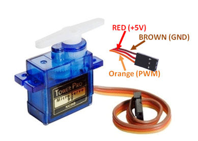 (Source:components101.com/)
Note that It is better to use the 5V pin as source for your servo.
Hardware Connections:
- Servo Signal Pin (Yellow/White(Orange)): Connect to
PD15(TIM4_CH4) (D9). - Servo Power (Red): Connect to VCC. Although we often use 3.3V as our source (VCC) in STM32F767 projects, Nucleo’s 3.3V/5V rail may not provide enough current. If you have more sensors and motor are connected, then you might consider using external bateries. For this tutorial, just use the 5V pin oon the board (next to the 3.3V pin).
- Servo Ground (Brown/Black): Connect to GND.
Software Setup:
- Create a new project without using the default mode.
- On the left, go to
System Core > RCC > HSE: Crystal/Ceramic Resonator. Set your clock configurations as usual. - Configure
TIM4.- We will use
TIM4for this as it is a general-purpose 16-bit timer. - Set the Clock Source to
Internal Clock. - Set Channel 4 to
PWM Generation CH4. You will see thatPD15is activated.
- We will use
- In the timer configuration below:
- Knowing that APB1 Timer Clock Frequency: 108 MHz (Although the peripheral max frequency for APB1 is 54 MHz. I know it is a bit confusing with timer calculations, and I did a mistake before
54-1in some exercises priorly, I have fixed it by adding ARR into formula!) - Set prescaler (PSC) to
108-1to generate an easily calculatable 1μs resolution (1 MHz counter frequency): \(PSC = (108 MHz / 1 MHz) - 1 = 108 - 1\) - Set Counter Period (ARR) to \(10 000 - 1\) to get a 20 ms period (50 Hz) with a $1 \mu s$ resolution.
- Knowing that APB1 Timer Clock Frequency: 108 MHz (Although the peripheral max frequency for APB1 is 54 MHz. I know it is a bit confusing with timer calculations, and I did a mistake before
- Generate the code, configure your platformio.ini, and then
main.cin your PlatformIO project. - Set some private definitions after
/* USER CODE BEGIN PD */.#define SERVO_PULSE_MIN 500 // 1.0 ms pulse (1000 counts @ 1.0us resolution) #define SERVO_PULSE_MAX 2500 // 2.0 ms pulse (2000 counts @ 1.0us resolution) #define SWEEP_DELAY 5 // Delay in milliseconds per step - Set some Private variables after
/* USER CODE BEGIN PV */.uint16_t current_pulse = SERVO_PULSE_MIN; - Start timer and generating PWM in
/* USER CODE BEGIN 2 */HAL_TIM_PWM_Start(&htim4, TIM_CHANNEL_4); // Note the channel is 4 // Initialize the servo to the starting position (MIN) __HAL_TIM_SET_COMPARE(&htim4, TIM_CHANNEL_4, SERVO_PULSE_MIN); - Set PWM values from 0 to 180 and back again in
/* USER CODE BEGIN 3 */// === SWEEP UP: MIN (1ms/1000 counts) to MAX (2ms/2000 counts) === for(current_pulse = SERVO_PULSE_MIN; current_pulse <= SERVO_PULSE_MAX; current_pulse++) { __HAL_TIM_SET_COMPARE(&htim4, TIM_CHANNEL_4, current_pulse); HAL_Delay(SWEEP_DELAY); // Slow down the sweep for visibility } // === SWEEP DOWN: MAX to MIN === for(current_pulse = SERVO_PULSE_MAX; current_pulse > SERVO_PULSE_MIN; current_pulse--) { __HAL_TIM_SET_COMPARE(&htim4, TIM_CHANNEL_4, current_pulse); HAL_Delay(SWEEP_DELAY); } - Build and upload.
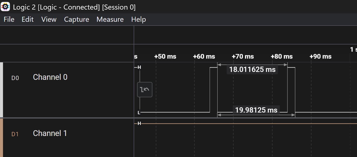
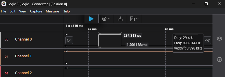
- Observe that your servo is rotating, and you see this kind of signal if you check
PD15on oscilloscope.