Lecture 2 - GPIO (General Purpose Input Output)
Formål: Etter å ha gått gjennom denne sida, skal du kunne:
- Forstå kva GPIO (General Purpose Input/Output) er og kva rolle det har i mikrokontroller-applikasjonar.
- Lese inn frå ein trykknapp og styre ein LED ved hjelp av GPIO-pinnar.
- Skilje mellom header-filer og eksterne bibliotek i C-prosjekt.
- Bruke
typedefogstructfor å definere eigne datatypar. - Forstå det grunnleggande om peikarar og korleis dei blir brukt i C.
- Deklarere og definere funksjonar, inkludert forståing av parameter og returtypar.
Some important C concepts
Function definitions
In a C program, you have to have a main function. The main function in C is a special function that serves as the entry point for program execution. When a C program is compiled and executed, the operating system or runtime environment calls the main function to begin the program’s operations. It looks something like this:
#include <stdio.h>

int main() {
    printf("Hello, world!\n");
    return 0;
}
A function definition includes the return type, the function name, a list of parameters (with their types), and a block of code (the function body) that performs the desired operations. If you want to define a new function in C, you must either do it before the main like this:
#include <stdio.h>

// Defining a function that
// print square of given number
void printVal(int num, float real){
    printf("%d %f\n", num, real);
}

int main() {
    int a = 3;

    // Call the printVal function and pass
    // desired values
    printVal(a, 1.5);
    return 0;
}
or after the main, but with a function decleration beforehand like this:
#include <stdio.h>
// Function decleration
void printVal(int num, float real)

int main() {
    int a = 3;
    printVal(a, 1.5);
    return 0;
}

// Fuction definition after
void printVal(int num, float real){
    printf("%d %f\n", num, real);
}
See more: geeksforgeeks.org/c/c-functions and w3schools.com/c/c_functions_decl.php
#define preprocessor
The define preprocessor directive is used to define constants or macros in C. It can be used to define values or even code that can be reused throughout the program. #define works by literally replacing the defined term with its value during the preprocessing step, before the compilation begins.
See more: geeksforgeeks.org/c/typedef-versus-define-c/.
#include <stdio.h>

// Defining a constant
#define MAX_SIZE 100

int main() {

    // Using the constant in the array size
    int arr[MAX_SIZE];
    printf("%d", MAX_SIZE);
    return 0;
}
Parameter and return types
Parameter: input of a function Return: output of a function
For example, int add(int a, int b) declares a and b as integer parameters.
1. Basic (Primitive) Data Types
These are the fundamental built-in types in C:
- Integer types:
char: Used for single characters (can also be treated as small integers). Can be signed or unsigned.short(orshort int): A short integer. Can be signed or unsigned.int: The most common integer type. Can be signed or unsigned. Its size can vary depending on the system (usually 2 or 4 bytes).long(orlong int): A long integer, typically larger than int. Can be signed or unsigned.long long(orlong long int): An even longer integer, introduced in C99. Can be signed or unsigned.
- Floating-point types:
float: Single-precision floating-point numbers.double: Double-precision floating-point numbers (more precise than float).long double: Extended-precision floating-point numbers (highest precision).
- Boolean type:
_Bool(orbool): For boolean values (true/false), introduced in C99.
2. Derived Data Types
These are built upon the basic types:
- Pointers:
type *parameter_name: A pointer to a variable of type. Pointers are crucial for “call by reference” in C, allowing a function to modify the original variable passed as an argument.- Examples:
int *ptr;
char *str;
- Arrays:
type array_name[]: When an array is passed as a parameter, it “decays” into a pointer to its first element. The size information of the array is usually lost within the function’s scope.type array_name[size]: While you can specify a size, it’s often ignored when passing arrays to functions (except for multi-dimensional arrays where the inner dimensions must be specified).char *string: C-style strings are essentially character arrays, and are often passed aschar*.
- Function Pointers:
return_type (*function_pointer_name)(parameter_types): Allows you to pass a function itself as an argument to another function. This is a more advanced concept used for callbacks and generic programming.- Example:
int (*func_ptr)(int, int);
3. User-Defined Data Types
You can define your own custom data types and use them as parameters:
- Structures (
struct):struct StructureName parameter_name: Allows you to group different data types into a single unit. You can pass structures by value (a copy is made) or by pointer (for efficiency and modification).- Example:
struct Point {
    int x;
    int y;
};
struct Point p1;

int main(){
  // Create a struct variable
  struct Point a;

  // Initialize a member
  a.x = 5

  return 0;
}
- Unions (
union):union UnionName parameter_name: Similar to structs, but all members share the same memory location.- Example:
union Data {
    int i;
    float f;
    char str[20];
};
union Data data;
- Enumerations (
enum):enum EnumName parameter_name: Defines a set of named integer constants.- Example:
enum Color { RED, GREEN, BLUE };
enum Color myColor;
- Typedef’d types:
MyCustomType parameter_name:typedefallows you to create aliases for existing data types (including complex ones like structs or pointers), making code more readable. It is very similar to regularstruct, but it allows you to define a structure and simultaneously create a new, shorter, and more convenient name for that structure type. This new name can then be used directly without the struct keyword.- Example:
typedef struct {
    int x;
    int y;
} Point;

int main() {
  // Declare variables using the new alias names directly
  Point p1;
  Car myCar;

  p1.x = 10;
  p1.y = 20;

  printf("Point p1: (%d, %d)\n", p1.x, p1.y);
  return 0;
}
Note thattypedef struct { int x; int y; } Point; means that Point is now a synonym for struct { int x; int y; } in the struct explanation. From this point forward, you can simply write Point p1; instead of struct { int x; int y; } p1;.
Pointers
Pointers (NOR: peikarar) are arguably one of the most confusing concepts in C/C++, especially for those who learned Python as their first programming language. It is the backbone of low-level memory manipulation in C. Let’s have a look.
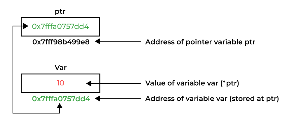
When a variable is created in C, a memory address is assigned to the variable. A pointer is a variable that stores the memory address of another variable.
There are two operators we use around the pointer concept: asterix * and reference operator &.
- To access the variable’s address, we use the reference operator
&. - If you create a variable to hold the variable’s address, we use the asterix
*
#include <stdio.h>

int main() {

    // Normal Variable
    int var = 10;

    // Pointer Variable ptr that stores address of var
    int* ptr = &var;

    // Directly accessing ptr will give us an address
    printf("%d", ptr); // or printf("%d", &var);

    // Dereferencing ptr to access the value
    printf("%d", *ptr); // or prinft("%d", var);

    return 0;
}
Output:
0x7fffa0757dd4
10
 (Source: geeksforgeeks.org)
The size of a pointer in C depends on the architecture (bit system) of the machine, not the data type it points to.
- On a 32-bit system, all pointers typically occupy 4 bytes.
- On a 64-bit system, all pointers typically occupy 8 bytes.
The size remains constant regardless of the data type (int, char, float*, etc.). We can verify this using the
sizeofoperator.
#include <stdio.h>

int main() {
    int *ptr1;
    char *ptr2;

    // Finding size using sizeof()
    printf("%zu\n", sizeof(ptr1));
    printf("%zu", sizeof(ptr2));

    return 0;
}
Output:
8
8
See more: geeksforgeeks.org/c/c-pointers, w3schools.com/c/c_memory_address.php w3schools.com/c/c_pointers.php
See MX_GPIO_Init()
We started seeing those concepts in our code. We will go more into it.
static void MX_GPIO_Init(void)
{
  GPIO_InitTypeDef GPIO_InitStruct = {0};
  /* GPIO Ports Clock Enable */
  __HAL_RCC_GPIOH_CLK_ENABLE();
  __HAL_RCC_GPIOB_CLK_ENABLE();
  __HAL_RCC_GPIOA_CLK_ENABLE();

  /*Configure GPIO pin Output Level */
  HAL_GPIO_WritePin(LD1_GPIO_Port, LD1_Pin, GPIO_PIN_RESET);

  /*Configure GPIO pin : LD1_Pin */
  GPIO_InitStruct.Pin = LD1_Pin;
  GPIO_InitStruct.Mode = GPIO_MODE_OUTPUT_PP;
  GPIO_InitStruct.Pull = GPIO_NOPULL;
  GPIO_InitStruct.Speed = GPIO_SPEED_FREQ_LOW;
  HAL_GPIO_Init(LD1_GPIO_Port, &GPIO_InitStruct);
}
- Here you see that
GPIO_InitStructis a struct and we reach its elements with the dot operator. &GPIO_InitStructis a pointer that holds the address of this struct.- Also you see that
MX_GPIO_Init();is defined in between lines ~166-199, but it is declared at line 88.
GPIO and registers
GPIO: General Purpose Input Output
Input can be a button or a sensor, output can be a LED, a motor or another actuator.
Now time to get more familiar with registers and reading datasheet.
Exercise: User button - LED control
- Look at the user manual of the board to determine which port the user LEDs are connected.
- Start a new STM32CubeMX project. If you select the default mode, the LED assignments will be already done.
- Skip clock configurations (for now).
- Do the necessary changes in the Project Manager tab and generate the source code.
- Create a platformio.ini and Copy the necessary content in it.
- Open the project using PlatformIO home page.
- Do these necessary changes after
/*USER CODE BEGIN 3*/in main.c./* USER CODE BEGIN 3 */ if(HAL_GPIO_ReadPin(USER_Btn_GPIO_Port, USER_Btn_Pin)){ HAL_GPIO_WritePin(LD2_GPIO_Port, LD2_Pin, GPIO_PIN_SET); } else{ HAL_GPIO_WritePin(LD2_GPIO_Port, LD2_Pin, GPIO_PIN_RESET); } - Build and upload.
- Observe the blue LED state as you press user button (blue button) on your board.
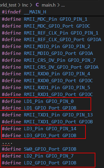
main.h
A header file in C is a crucial component of program organization, serving as a central place to declare functions, variables, and data types that are used across multiple source code files. Think of it as a contract or an interface that tells different parts of your program what’s available and how to use it, without revealing the full implementation details. Header files typically have a .h extension (f.ex: main.h, stm32f7xx_hal.h etc.)
The main.h is a user defined header file, in this case, CubeMX creates it for us. We can/will extend it according to our purpose.
Although the reference manual and user manual are our best friends in programming our board, there are still other (easier?) ways to check pins. Since we select the board, not the uC, when we started a new project in CubeMX, and we keep the default mode, our main.h is created accordingly. The pinouts of the board are defined in this file.
So now, please check the pin numbers and ports for user LEDs and buttons from the main.h.
Exercise(Home/Lab): Button counter
As you see, there are three LEDs and one user button on out STM32F767 Nucleo board. In this exercise, I want you to make a binary counter. Every time you press the button, the counter should change the LEDs accordingly.
 (Source: youtube.com/Mathmo14159)
You can be creative about how smart you want to do the counting operation, or you can use just several if-elses. Good luck!
External LED and Button
So far we have not connected anything to our board. Now we will connect a button as input and an LED as output.
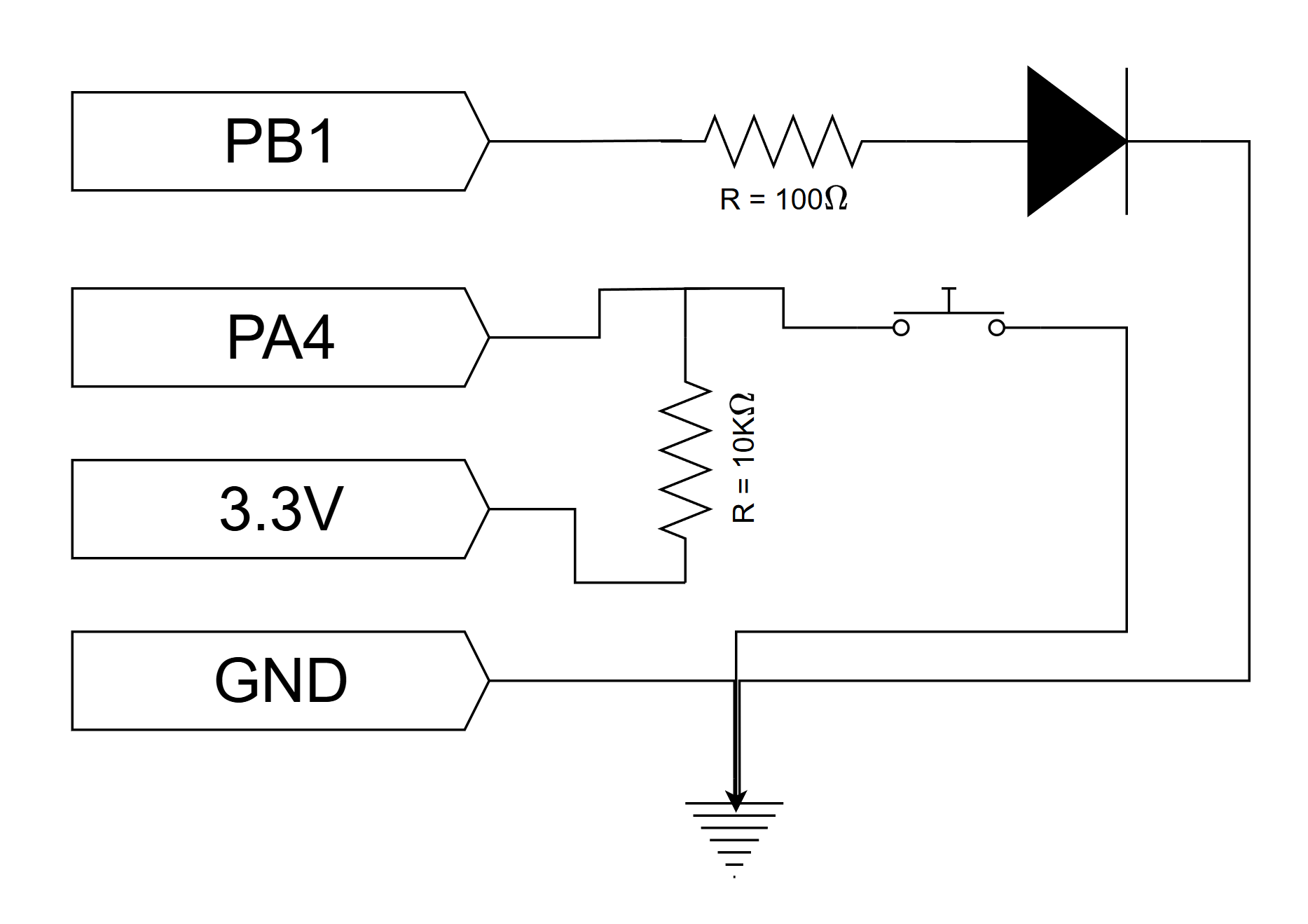
You can have a look at the positions of the PB1 and PA4 on the user manual page 32.
Exercise-1: Toggle an external LED
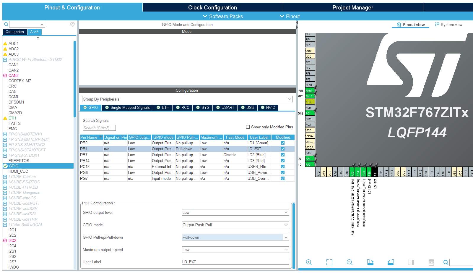
- Start a new STM32CubeMX project.
- Change the PB1 state from Reset_state to GPIO_Output.
- Right click > Edit user label > give a descriprive name f.ex: EXT_LED
- Pin Configuration > GPIO > PB1 > GPIO Pull-up/Pull-down: Pull-Down
- Skip clock configurations (for now).
- Do the necessary changes in the Project Manager tab and generate the source code.
- Create a platformio.ini and Copy the necessary content in it.
- Open the project using PlatformIO home page.
- Do the necessary changes after
/*USER CODE BEGIN 3*/in main.c. - Build and upload.
- Observe the external LED state.
As you probably noticed, when we are controlling a LED from the STM32F767 Nucleo board, we are using a resistor in series with the LED. This resistor is required in order to not destroy the LED, and should be of an appropriate resistance.
The characteristics of a LED (like any diode) is inherently non-linear. A small voltage variation may cause a large variation in current through the diode. If this is not managed the diode will be destroyed by excessive current. As the light intensity of the diode depends on current, it is apparent that the diode should be supplied by a current source. A high performance current source is a complex device however, and thus we often opt to approximate the current source by means of a resistor.
The color of a LED is not determined by the color of the package, but rather by it’s internal physical structure. The different colors thus have different characteristics, such as different nominal voltage drop. This has implications on the selection of the resistor. Also the value of the selected resistor will impact the light intensity of the LED. The minimum resistor value (i.e. maximum light intensity) depends on the maximum current, as well as the voltage/current-characteristics of the LED.
The digital outputs of the Nucleo-144 board has a high voltage level of 3.3 V. The voltage drop of a LED will typically vary between 1.8 V and 3.3 V, depending on the color. It will also vary slightly depending on the current, but this variation may be ignored in most applications. The maximum current of the GPIO pins on the board is 25 mA, but a safe limit for our LEDs would be arounf 15 mA. By subtracting the LED voltage from the supplied voltage, we find the required voltage drop of the resistor.
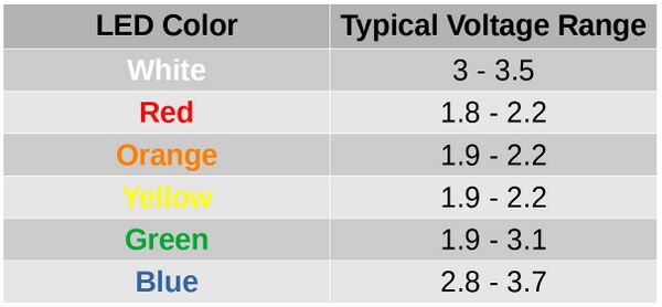
The table above shows the typical forward voltage ranges for different LED colors. When selecting a resistor for your external LED circuit, you should use the forward voltage corresponding to the color of your LED. For example, a red LED typically has a forward voltage between 1.8V and 2.2V, while a blue LED has a forward voltage between 2.8V and 3.7V.
To calculate the appropriate resistor value, use the formula:
\[R = \frac{V_{supply} - V_{LED}}{I_{LED}}\]Where:
- \(V_{supply}\) is the supply voltage (e.g., 3.3V from the Nucleo board)
- \(V_{LED}\) is the forward voltage of your LED (from the table above)
- \(I_{LED}\) is the desired current through the LED (typically 10–20 mA for standard LEDs)
Example calculation for a red LED:
- \[V_{supply} = 3.3V\]
- \(V_{LED} = 2.0V\) (typical for red)
- \(I_{LED} = 0.015A\) (15 mA)
Choose the next standard resistor value above your calculation (e.g., 100 Ω) to ensure you do not exceed the LED’s current rating.
Notice: For high power LED’s you should also make sure that the power dissipated in the resistor does nod exceed the ratings of the resistor. For very high power applications a simple current limiting resistor is not suitable, and you should instead use power electronics. This however is a entire field of engineering on it’s own, and way outside the scope of what we will be covering here.
Exercise-2: Toggle an external LED with external button
You may think that “just to connect a button, what can it go wrong?” but unfortunately when it comes to push buttons, a common beginner mistake root from connecting the button wrong. For now, as a rule of thumb, keep in mind these two figures and check these:
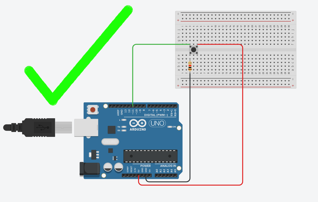
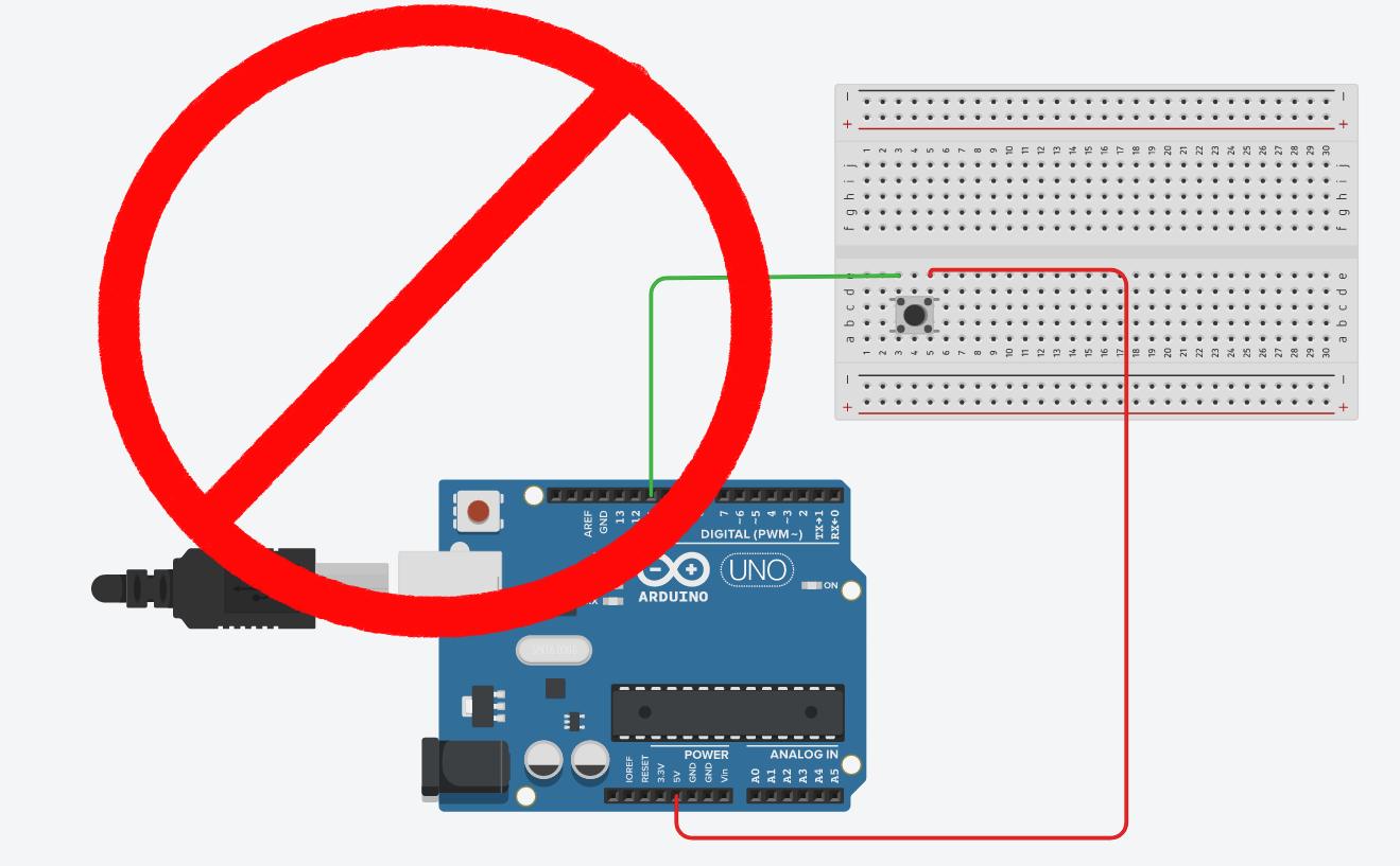
ALWAYS CHECK: - If the button orientation is correct. Remember: 1a-1b and 2a-2b are connected bus and should be place on the breadboard accordingly. - If both +5V and GND is connected. The button should have deterministic PRESSED and RELEASED voltage. Never leave a leg empty. - THE MOST CRITICAL: Are you sure that you didn’t connect +5V to GND? Always double check before connecting the Arduino to the power.
- Reopen the previous STM32CubeMX project.
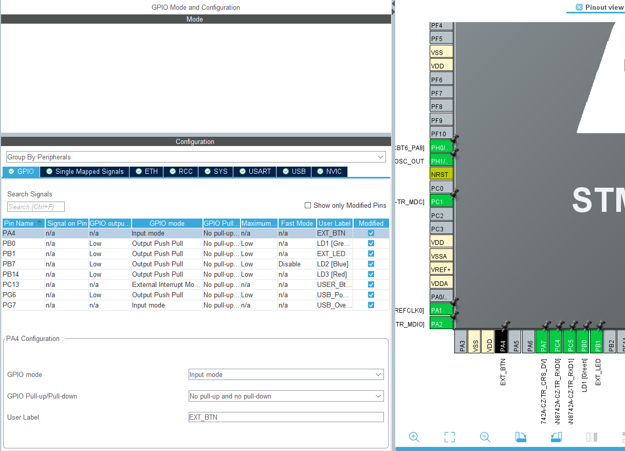
- Change the PA4 state from Reset_state to GPIO_Input.
- Right click > Edit user label > give a descriprive name f.ex: EXT_BTN
- Pin Configuration > GPIO > PA4 > GPIO Pull-up/Pull-down: No pull-up, no pull-down (because we put pull-up resistor externally)
- Skip clock configurations (for now).
- You don’t need to change anything in the Project Manager tab, just generate the source code.
-
Do the following changes after
/*USER CODE BEGIN 3*/in main.c.GPIO_PinState ext_btn = HAL_GPIO_ReadPin(EXT_BTN_GPIO_Port, EXT_BTN_Pin); if (ext_btn == GPIO_PIN_SET){ HAL_GPIO_WritePin(EXT_LED_GPIO_Port, EXT_LED_Pin, GPIO_PIN_SET); } else{ HAL_GPIO_WritePin(EXT_LED_GPIO_Port, EXT_LED_Pin, GPIO_PIN_RESET); } - Build and upload.
- Observe the external LED state.
Debugging
At this moment, I hope your project doesn’t work. Yeah, sounds cruel, but for a reason…
At this step, we will learn a bit about debugging. We can categorize debugging in microcontrollers into two:
- Hardware debugging: using multimeter and oscilloscope to measure voltages and currents at the crucial spots of your circuit.
- Software debuggings: using a debugger program to see the register changes. For this, we use ST-LINK and PIO debugger (which uses OpenOCD).
Let’s start with hardware debugging:
- Does your power LED lid red?
- Is the voltage difference between your source and GND pins 3.3V on the breadboard?
- Do you see 3.3V on the button’s leg which is connected to the 10K ohm resistor?
- Do you see 0V on the button’s leg which is connected to the GND?
- Is your LED connected with the right orientation?
- If you remove LED, is the voltage difference between the pins where you’d connect LED is ~2.0 V when you press the button?
You can do more steps but you got the point, I hope. Let’s proceed the software debugging. However, before that we need to make sure that our platformio.ini file is configured properly for debugging. Make sure that you have all these lines in it:
[env:nucleo_f767zi]
platform = ststm32
board = nucleo_f767zi
framework = stm32cube
build_flags =
 -IInc
upload_protocol = stlink
debug_tool = stlink
debug_build_flags = -O0 -g -ggdb
Now, build and upload the code one more time. Afterwards select the Run and Debug (Ctrl+Shift+D) tab on the left. Select the correct project on the debugger (at the top, next to the play button), and then press start debugger button (F5).
The reason why we defined a variable to keep the button state is because we want to add this variable to our watchlist. Right click on the variable and “add to watchlist”. You will see this screen:
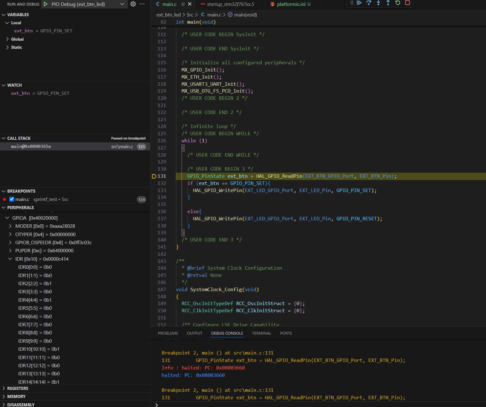
Add breakpoints and start debugger. Check register GPIOA_IDR[4:4] to see the state of the button.
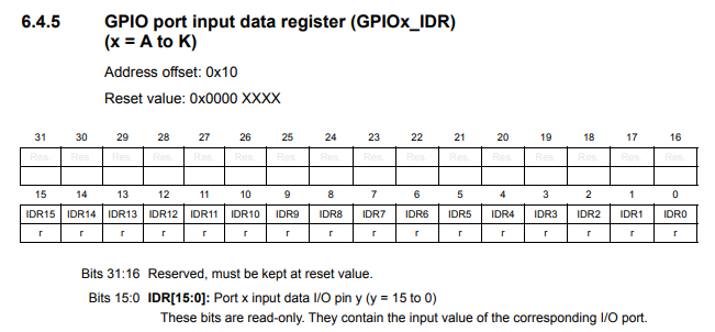
(Source: datasheet pg 233)