LWIP stack, LED ON/OFF through ethernet

Introduction to Embedded Networking

In this lecture we will focus on embedded networking using the ethernet port on our board using LWIP stack. Let’s get familiar with some terminology first:

1. Ethernet

Ethernet is the most common standard for wired local area networks (LANs). It defines the physical and data link layers of the network stack—essentially, the rules for transmitting data over cables.

  • Physical Connection: The STM32F767 Nucleo board includes an Ethernet PHY (Physical Layer) chip and a standard RJ45 connector, allowing it to plug directly into a network switch or router.
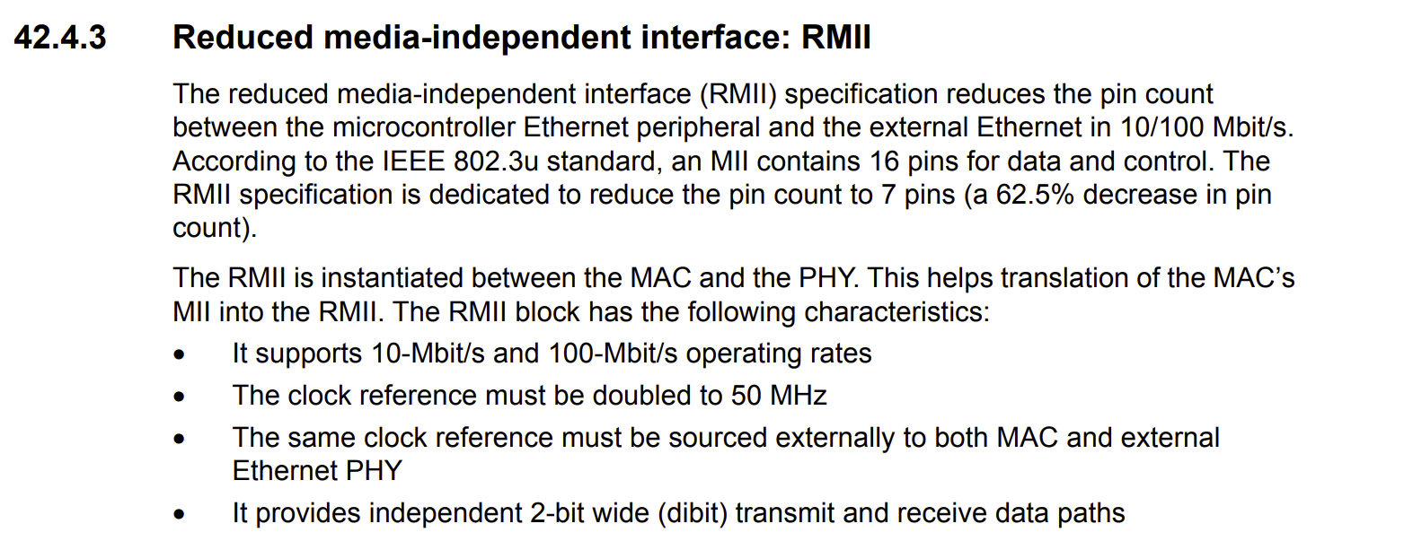
  • MAC and PHY: The microcontroller contains the MAC (Media Access Control) layer, which handles addressing (the unique 48-bit MAC address). The external PHY chip handles the actual electrical signaling over the cable. On this board, they communicate using the RMII (Reduced Media-Independent Interface).

You can find more info about MII and RMII in the reference manual, but it is not relevant to our course. So we don’t get into details. Just know that our board supports both, RMII is better/more efficient. Therefore, we will use it. rmii

So, ethernet provides the physical link, enabling the microcontroller to send and receive raw data packets.

2. LwIP (Lightweight IP)

To make sense of the raw data packets from the Ethernet link, the microcontroller needs a TCP/IP stack. Since a full operating system stack is too large and complex for a microcontroller, we use LwIP.

lwIP (lightweight IP) is a widely used open-source TCP/IP stack designed for embedded systems with limited resources (RAM and Flash). lwIP was originally developed by Adam Dunkels in 2001[3] at the Swedish Institute of Computer Science and is now developed and maintained by a worldwide network of developers. The network stack of lwIP includes an IP (Internet Protocol) implementation at the Internet layer that can handle packet forwarding over multiple network interfaces.[6] Both IPv4 and IPv6 are supported dual stack since lwIP v2.0.0 (Source: wikipedia.org)

It’s function is It implements essential network protocols like IP (Internet Protocol), TCP (Transmission Control Protocol), and UDP (User Datagram Protocol), allowing the microcontroller to understand and participate in internet communication.

So for us LwIP will manage the network connection, handles the IP addressing (192.168.1.10), and serves as the foundation upon which our web server runs.

3. The LwIP HTTPD Web Server

The LwIP stack includes an optional application layer protocol: the HTTP Daemon (HTTPD), which is our web server.

The HTTPD listens for incoming HTTP (Hypertext Transfer Protocol) requests (a user typing the IP address into a browser) and sends back HTML/CSS files as responses.

Since microcontrollers are designed for control, not just static display, the LwIP server supports two mechanisms for real-time interaction:

  • CGI (Common Gateway Interface): Allows the web page to execute a function (e.g., toggle an LED) on the microcontroller when a form or button is submitted.
  • SSI (Server Side Includes): Allows the server to insert dynamic data (e.g., the current LED state: “ON” or “OFF”) directly into the HTML page before sending it to the browser.

So the HTTPD application allows us to host our interactive web page, using CGI to toggle the LED and SSI to display the current state of the board.

STM32F767 Nucleo Web Server

The planning of this lecture is through making a Web server tutorial. The server will host a webpage with a text field and a button.

STM32CubeMX Configuration:

  1. Create a new project without using the default mode.
  2. On the left, go to System Core > RCC > HSE: Crystal/Ceramic Resonator to use the external clock source for better timing accuracy.
  3. Go to System Core > SYS > Debug: Serial Wire (usually default, but good to check).
  4. Set PB0 (pin connected to LD1) as GPIO_Output and change its label to LD1. (Useful status indicator).
  5. Under “Pinout & Configuration,” go to Connectivity > ETH (Ethernet). Set the Mode to RMII. Make sure the ETH parameters are as given below: eth-param-settings.png
  6. Under “Pinout & Configuration,” go to Middleware and Software Packages > LWIP.
  7. Mode: Enabled
  8. Platform Settings: LAN8742 for both fields.
  9. It should look like this: lwip-settings.png
  10. Under “Pinout & Configuration” again go to Middleware and Software Packages > FREERTOS. Select Interface: CMSIS_v1. It is often the easiest and most stable choice for initial projects, but you can choose CMSIS_v2 for more functionality and newer standards.
    • Why FreeRTOS is Necessary for LwIP?
    • Multitasking: LwIP itself runs as a separate task (the LwIP stack task), which handles all network events (DHCP, ARP, TCP/IP packets).
    • Blocking Calls: When your main() loop calls netconn_connect() or netconn_write(), the thread must wait for a network response. An RTOS is required to pause your thread while allowing the rest of the LwIP stack (and all other system tasks) to continue running. If you try to run these calls without an RTOS, your program will freeze, which is why those libraries you tried to include were looking for the RTOS system functions. So the main reason is that the LwIP APIs we are using (the netconn API for the HTTP POST request) are blocking functions that depend on a real-time operating system (RTOS) like FreeRTOS to manage tasks, sockets, and timeouts.
  11. Change the TOTAL_HEAP_SIZE to 51200 to set 50 KB heap size. Using 51,200 bytes (50 KB) is a very safe and robust size for the STM32F767 (which has ample RAM) when running LwIP and a simple application task. This should prevent any memory allocation failures during the network operations.
    • Calculation: \(50 KB = 50 \times 1024 bytes = 51,200 bytes\)
  12. Under FREERTOS > Advanced settings set USE_NEWLIB_REENTRANT: Enabled. This is necessary otherwise you will get this error (including if you had configured your clock settings as usual.) freertos-settings.png
  13. To fix the SysTick conflict, first understand the reason: Both the HAL and FreeRTOS need a high-frequency timer interrupt, and by default, CubeMX uses the SysTick timer for both, which causes a conflict. We can resolve the warning by assigning the HAL timebase to a separate, unused timer (like TIM6).
  14. In the CubeMX Pinout & Configuration window, navigate to System Core > SYS.
  15. In the Parameter Settings tab, find the setting Timebase Source.
  16. Navigate to Timers > TIM6.
  17. You should see that the Mode is set to Internal Clock and the settings are configured to provide a 1ms timebase. No further changes should be needed here. systic_tim6.png
  18. Go to Clock configuration and det HCLK to 216 MHz this time. We need speed for reliable communication!
  19. Give a proper name and generate the code as usual: Basic application structure, STM32CubeIDE Toolchain, untick “Generate under root” and generate the code.

Preparing the webserver and ethernet connection:

  1. This part of this exercise is not relevant to microcontroller part. You have learned how to set up a Web server in the network part of this course. You can use any Web server, but at this step we will run a simple Python script that hosts a local server. Follow this link for that: # TODO (Projects > Set a simple web server using Python for test purposes)
  2. Note the IP address printed by the Python script (something like 192.168.1.10). You will use this in the C code.
  3. Connect your STM32F767 board to your local network (directly to your PC, or router or switch) using a standard Ethernet cable.

Code implementation for HTTP Client Board:

This logic uses the LwIP netconn API to establish a TCP connection, send the HTTP POST request, and close the connection.

  1. First and foremost, as we did in every new project, we must create a platform.ini file to be able to open CubeMX generated projects in PlatformIO. However, this time we must modify it a bit. Since we used two new middleware software, we must add their headers in our include. So, copy this content in your platformio.ini:
      [env:nucleo_f767zi]
      platform = ststm32
      board = nucleo_f767zi
      framework = stm32cube
      build_flags = 
       -IInc
       -IDrivers/STM32F7xx_HAL_Driver/Inc
       ; --- ADD THESE LWIP/FREERTOS PATHS ---
       -IMiddlewares/Third_Party/LwIP/src/include
       -IMiddlewares/Third_Party/LwIP/src/include/lwip
       -IMiddlewares/Third_Party/LwIP/src/include/netif
       -IMiddlewares/Third_Party/LwIP/system/OS/sys_arch
          
       ; FreeRTOS includes (often needed when using LwIP API)
       -IMiddlewares/Third_Party/FreeRTOS/Source/include
       -IMiddlewares/Third_Party/FreeRTOS/Source/CMSIS_RTOS
       -IMiddlewares/Third_Party/FreeRTOS/Source/portable/GCC/ARM_CM4F
       -IMiddlewares/Third_Party/FreeRTOS/Source/portable/GCC/ARM_CM7/r0p1
      upload_protocol = stlink
      debug_tool = stlink
      debug_build_flags = -O0 -g -ggdb
      monitor_speed = 115200
    
  2. In main.c, two new includes showed up: #include "cmsis_os.h" and #include "lwip.h". You will see that due to the way we generated the code by adding LWIP and FRERTOS middleware packages, a new folder YOUR_PROJECT_PATH\Middlewares\Third_Party.

    If you are getting include errors like in the image below, even after you configured your platformio.ini correctly, it might be about the confusion of IntelliSense/C++ extension. The C++ extension (ms-vscode.cpptools) uses its own logic to resolve include paths, which often doesn’t perfectly match the build flags (platformio.ini) used by the GCC compiler when you actually build the project. Just ignore the squiggly lines and try compiling the code, nonetheless. include_fail.png

  3. Define the server connection parameters under /* USER CODE BEGIN PV */ (Private variables):

     // NOTE: REPLACE THIS IP WITH THE IP ADDRESS OF YOUR PC RUNNING THE PYTHON SERVER
     #define SERVER_IP       "192.168.1.10" 
     #define SERVER_PORT     8080
     #define POST_PATH       "/update"
    
     // Example data to send (float sensor reading)
     float sensor_reading = 25.5f;
    
  4. We will create a private function to send http posts later on. Let’s give e heads-up to the compiler before the main() function. (Psst: this is a very C-thing. We talked about it here.Put this under /* USER CODE BEGIN PFP */:

     void send_http_post(float value);
    
  5. In the main while(1) loop, call the function (we will define in the next step) periodically under /* USER CODE BEGIN 3 */ Since we changed the SysTick timer, instead of using HAL_Delay(), we will use osDelay():

     // Dummy sensor reading
     sensor_reading += 0.1f;
     if (sensor_reading > 35.0f) sensor_reading = 20.0f; 
     send_http_post(sensor_reading);
    
     // Wait 2 seconds before sending the next message. Use osDelay for LwIP/FreeRTOS.
     osDelay(2000); 
    
     /* USER CODE END 3 */
    
  6. Define a new function to handle the HTTP POST request outside of main(), ideally in /* USER CODE BEGIN 4 */:

       /**
       * @brief Sends an HTTP POST request with a raw data payload.
       */
     void send_http_post(float value)
     {
         struct netconn *conn = NULL;
         ip_addr_t server_ip;
         err_t err;
    
         // Convert server IP string to lwIP ip_addr_t structure
         IP4_ADDR(&server_ip, 
                 SERVER_IP[0] - '0', SERVER_IP[2] - '0', SERVER_IP[4] - '0', SERVER_IP[6] - '0'); // Simplified parsing, assumes simple fixed IP format for demo
    
         // In a real application, use: ipaddr_aton(SERVER_IP, &server_ip);
    
         // 1. Format the raw data payload (the body of the request)
         char data_payload[32];
         int data_len = snprintf(data_payload, sizeof(data_payload), "%.2f", value);
    
         // 2. Construct the full HTTP POST request string
         char request_buffer[256];
         int request_len = snprintf(request_buffer, sizeof(request_buffer),
                                   "POST %s HTTP/1.1\r\n"
                                   "Host: %s:%d\r\n"
                                   "User-Agent: STM32F767-Client\r\n"
                                   "Content-Type: text/plain\r\n" // Matches the Python server expectation
                                   "Content-Length: %d\r\n"
                                   "Connection: close\r\n"
                                   "\r\n"
                                   "%s",
                                   POST_PATH, SERVER_IP, SERVER_PORT, data_len, data_payload);
    
         // 3. Create a new connection handle (TCP socket)
         conn = netconn_new(NETCONN_TCP);
         if (conn != NULL)
         {
             // 4. Connect to the server
             err = netconn_connect(conn, &server_ip, SERVER_PORT);
    
             if (err == ERR_OK)
             {
                 // 5. Send the entire request
                 netconn_write(conn, request_buffer, request_len, NETCONN_COPY);
    
                 // 6. Wait for response and read it (optional, but good practice)
                 struct netbuf *inbuf;
                 if (netconn_recv(conn, &inbuf) == ERR_OK)
                 {
                     // Successfully received a response (e.g., "OK" from Python server)
                     HAL_GPIO_WritePin(LD1_GPIO_Port, LD1_Pin, GPIO_PIN_SET); // Turn LED ON for success
                     netbuf_delete(inbuf);
                 }
             }
             else
             {
                 // Connection failed
                 HAL_GPIO_WritePin(LD1_GPIO_Port, LD1_Pin, GPIO_PIN_RESET); // Keep LED OFF for failure
             }
    
             // 7. Close and delete the connection handle
             netconn_close(conn);
             netconn_delete(conn);
         }
     }
    
  7. Build and upload.

TODO: ADD include lwip/api.h in main.h

Troubleshooting

Conflicting types for ‘HAL_RCC_OscConfig’

If you are getting the error message in the image below after enabling ETH module in CubeMX: eth_rcc_error.png

TL;DR: There is a bug in PlatformIO HAL package version (1.17.2).

  1. Go to YOUR_USER_NAME\.platformio\packages\framework-stm32cubef7\Drivers\STM32F7xx_HAL_Driver\Src\stm32f7xx_hal_rcc.c. You can easily copy this path from your error message.
  2. Add the const keyword in about line 342, before RCC_OscInitTypeDef like this: HAL_RCC_OscConfig(const RCC_OscInitTypeDef *RCC_OscInitStruct);
  3. Also in about line 722, before RCC_ClkInitTypeDef like this: HAL_RCC_ClockConfig(const RCC_ClkInitTypeDef *RCC_ClkInitStruct, uint32_t FLatency);

Reasoning for nerds:

It seems like it is due to a bug related to PlatformIO HAL package version (1.17.2). The C files and H files have a mismatch pointer types when they define these two functions: 1) HAL_RCC_OscConfig(const RCC_OscInitTypeDef *RCC_OscInitStruct); and 2)HAL_RCC_ClockConfig(const RCC_ClkInitTypeDef *RCC_ClkInitStruct, uint32_t FLatency);. The header files has const keywords before RCC_OscInitTypeDef and RCC_ClkInitTypeDef , but not the C files. The header file prototype correctly specifies the pointer parameter as const (meaning the function will not modify the structure), but the C file function definition does not have the const keyword. This is considered a conflict by the C compiler because const T* and T* are different pointer types.

I know it is annoying but we must add this const keywords in these C files. The good news is that, this modification will be done only once since these files are in the default stm32f7xx instalation of PlatformIO. Yes. We “fix a bug” 😎