Lecture 1 - Intro
Formål:
Etter å ha gått gjennom denne sida, skal du kunne:
- Setje opp eit nytt STM32F767ZI-Nucleo-prosjekt ved hjelp av PlatformIO og STM32Cube-rammeverket.
- Identifisere hovudkomponentane i eit PlatformIO-prosjekt (slik som
src/,include/ogplatformio.ini). - Skrive og laste opp eit enkelt program som blinkar ein LED ved hjelp av HAL-biblioteket, og vise bruk av GPIO og delay-funksjonar i ein innebygd samanheng.
Make sure that eveything you needed are installed: Installation Guide
Start your first STM32F767ZI-Nucleo Project
Warning: Before you upload the code, make sure your board is properly connected. There are two microUSB ports on the board. One is connected to bootloader, the other is connected to the board’s serial I/O. MAKE SURE THAT YOU CONNECT THE USB ON THE BOOTLOADER SIDE.
Using CubeMX + PlatformIO
In this course, we will use STM32CubeMX to generate projects, and PlatformIO to modify projects. It is possible to both generate and modify the code only using PlatformIO (as explained here), however, as we progress in the different tasks, it will be very difficult to set all the configurations manually. In old times, embedded system engineers had their “own” libraries for various tasks, LCD setup, ADC initialization, PWM parameters etc. They used to copy or include these pieces of code into their projects as they needed. Today, we have tidier solutions. For our development board, we can use STM32CubeMX, which is a graphical tool that allows a very easy configuration of STM32 microcontrollers and microprocessors. Therefore, we don’t need to write the code for every single configuration. We will be using STM32CubeMX extensively in this course.
You can watch this video to setup your first blink code using both CubeMX and PlatformIO: Click here for the video or follow the steps below:
- Start a new STM32CubeMX project.
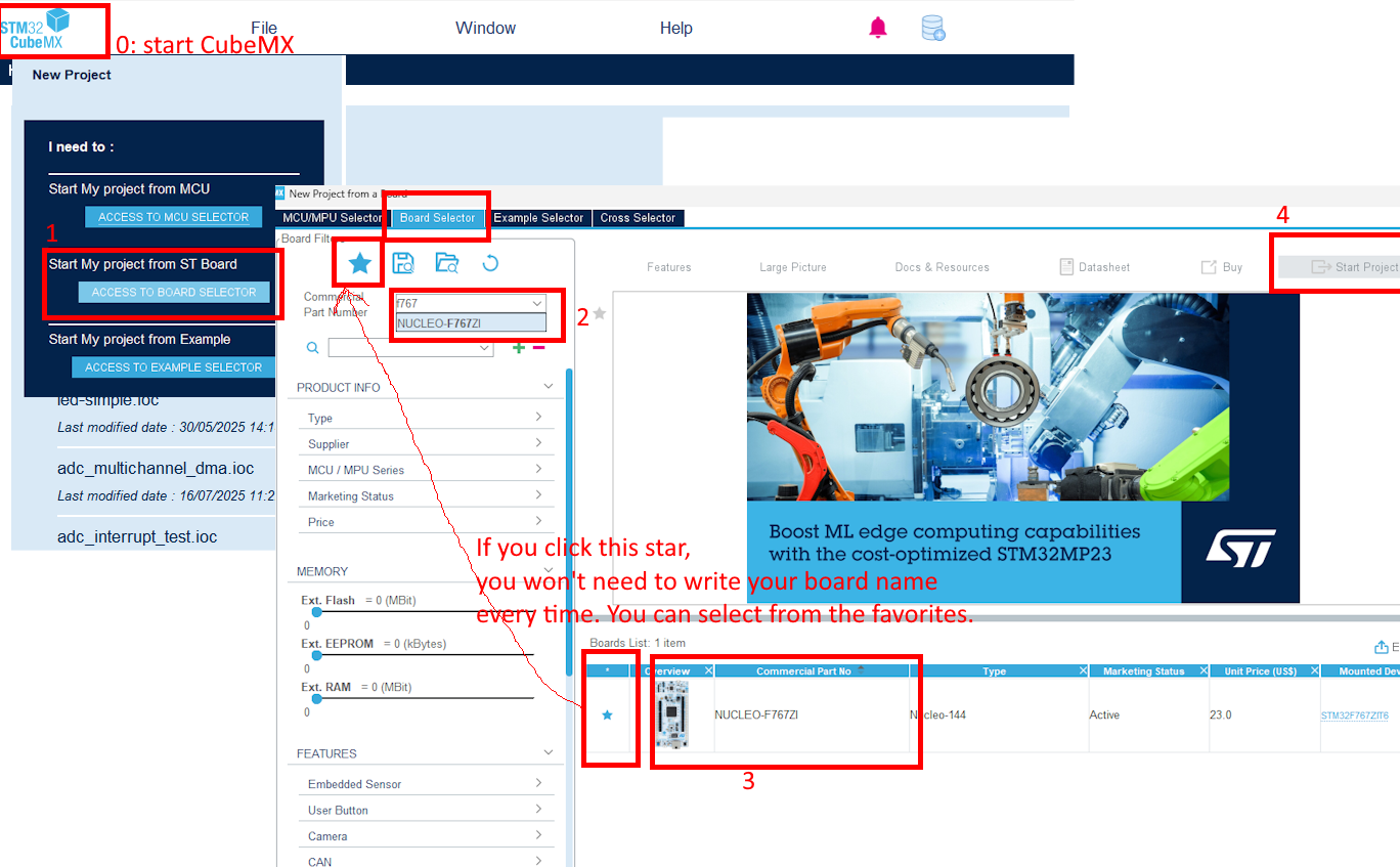 After you click Start Project if you select the default mode, the LED assignments will be already done.
 - Do nothing in pinout and skip clock configurations (for now).
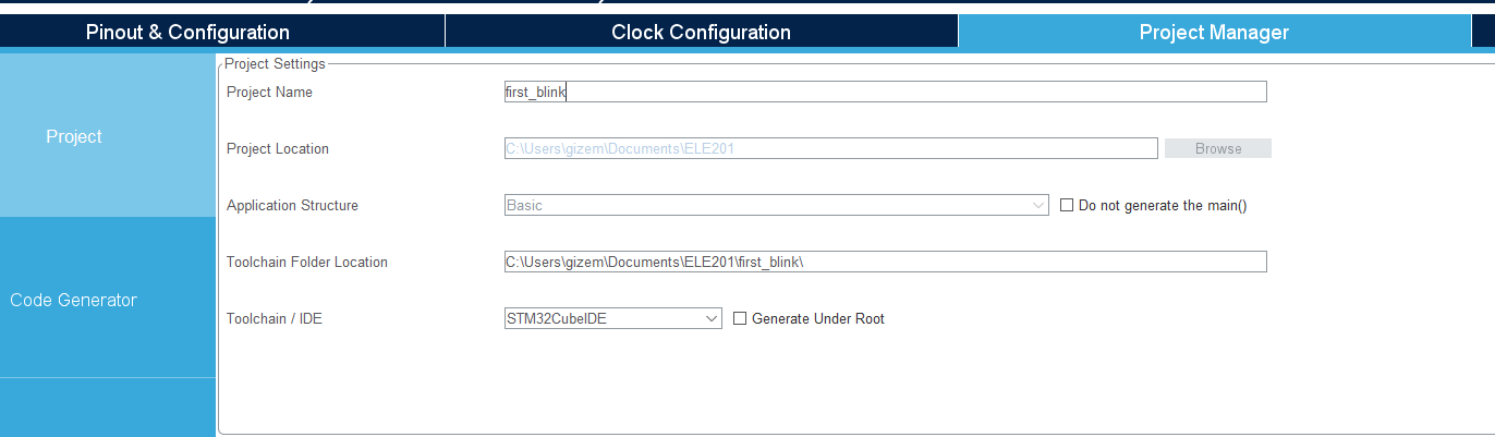
- Do the necessary changes in the Project Manager tab and generate the source code. a. Give a descriptive project name b. Choose where you want to locate your projects. You can use this location during this course. It might be smart to make a new folder under /Documents named ELE201, and gather all your future projects, including this one. c. Change Application Structure from Advanced to Basic. d. Change Toolchain/IDE to STM32CubeIDE e. Remove the tick in front of the Generate Under Root.
- Make sure that your setup looks similar to this:
- Go to File Explorer on your P OR VSCode>File>Open Folder and find where your new project is. Create a platformio.ini file and copy the content below in it.
[env:nucleo_f767zi]
platform = ststm32
board = nucleo_f767zi
framework = stm32cube
build_flags =
   -IInc
Please make sure that platformio.ini does not have another extension like platformio.ini.txt if you created it as a text document.
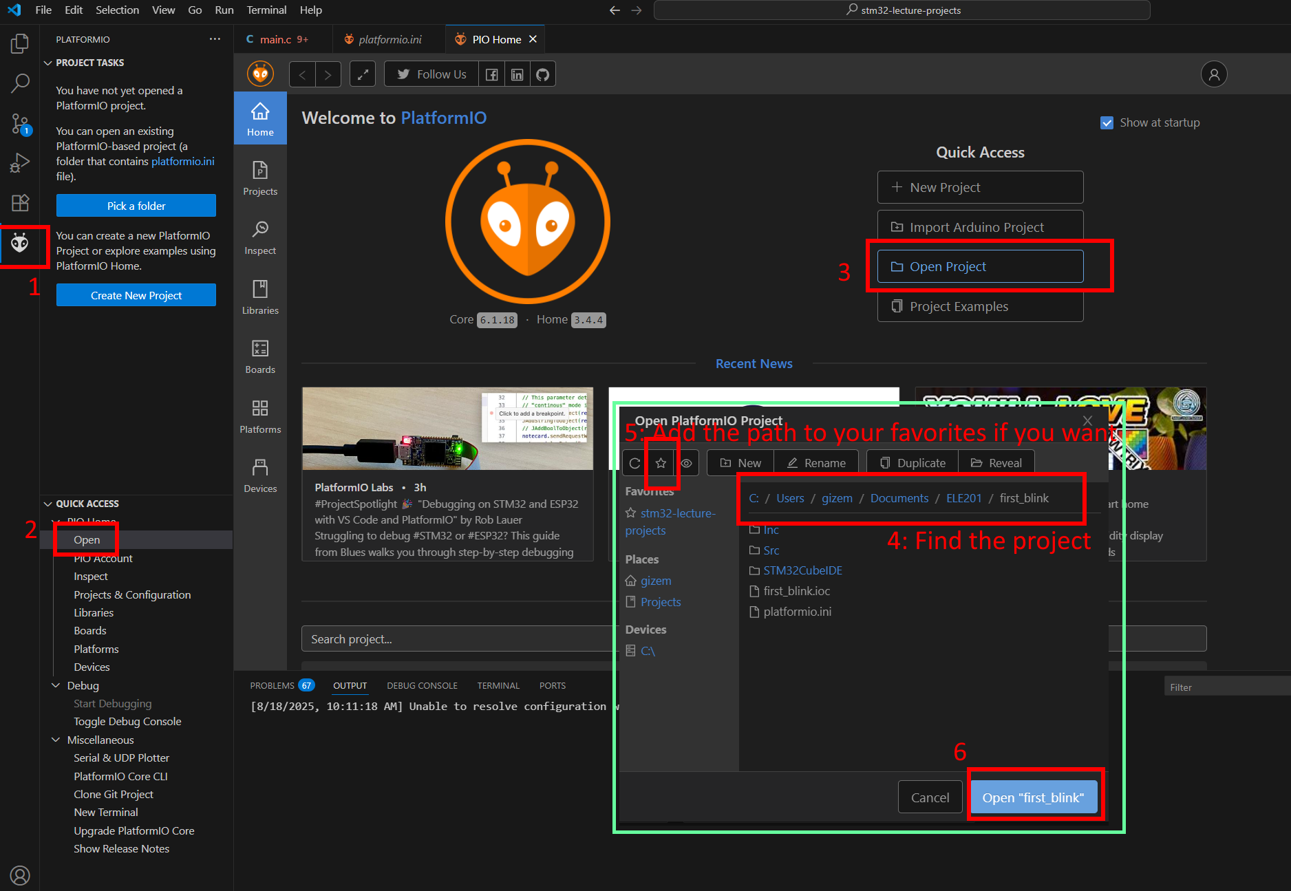
- Now you can open it as a project using PlatformIO.
-
The piece of code you need to add after
/*USER CODE BEGIN 3*/is here:HAL_GPIO_TogglePin(LD1_GPIO_Port, LD1_Pin); HAL_Delay(500); - Build and upload.
- Observe the blue LED state as you press user button (blue button) on your board.
If you can build the code, but cannot upload it, and getting this error:
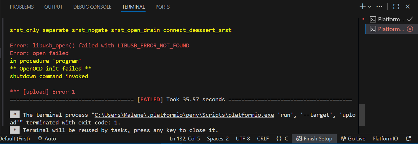 Then you need to update your ST-Link drivers. You can use this link.
Using only PlatformIO
This is an alternative method and we won’t be using it, but it is nice to know.
- Click on the PlatformIO icon in the left sidebar
- Click on “PIO Home” in the PlatformIO menu
- Click on “New Project”
- In the project wizard:
- Enter a project name (e.g., “first_blink”)
- Select “STM32F767ZI Nucleo” from the board dropdown
- Select “STM32Cube” as the framework
- Choose a location for your project. A folder in OneDrive might cause problems if the folder path is too long!
- Click “Finish”
- PlatformIO will automatically:
- Download the necessary STM32F7xx HAL libraries
- Set up the project structure
- Configure the build environment
- Wait for the initialization to complete (this might take a few minutes)
- Once completed, you’ll see a new project with the following structure:
src/- Your source code filesinclude/- Header filesplatformio.ini- Project configuration file
Now you can copy the content below in your main.c under the src folder.
#include "main.h"

void LED_Init();

int main(void)
{
  HAL_Init();
  LED_Init();

  while (1)
  {
    HAL_GPIO_TogglePin(LED_GPIO_PORT, LED_PIN);
    HAL_Delay(500);
  }
}

void LED_Init()
{
  LED_GPIO_CLK_ENABLE();
  GPIO_InitTypeDef GPIO_InitStruct;
  GPIO_InitStruct.Pin = LED_PIN;
  GPIO_InitStruct.Mode = GPIO_MODE_OUTPUT_PP;
  GPIO_InitStruct.Pull = GPIO_PULLUP;
  GPIO_InitStruct.Speed = GPIO_SPEED_HIGH;
  HAL_GPIO_Init(LED_GPIO_PORT, &GPIO_InitStruct);
}

void SysTick_Handler(void)
{
  HAL_IncTick();
}
This code blinks an LED on an STM32 microcontroller using the HAL library. It initializes the HAL system and configures a GPIO pin as an output for the LED. In the main loop, it toggles the LED state every 500 ms using HAL_GPIO_TogglePin and HAL_Delay. The SysTick_Handler updates the HAL tick for timing. The LED_Init function sets up the GPIO pin for the LED.
Now you can copy the content below in your main.h under the include folder.
#ifndef MAIN_H
#define MAIN_H

#include "stm32f7xx_hal.h"

#define LED_PIN                                GPIO_PIN_0
#define LED_GPIO_PORT                          GPIOB
#define LED_GPIO_CLK_ENABLE()                  __HAL_RCC_GPIOB_CLK_ENABLE()

#endif // MAIN_H
PlatformIO Buttons
For those who are a bit familiar with VSCode, the buttons might be easier. However, PlatformIO extension offers a lot. Let’s have a quick look at them.
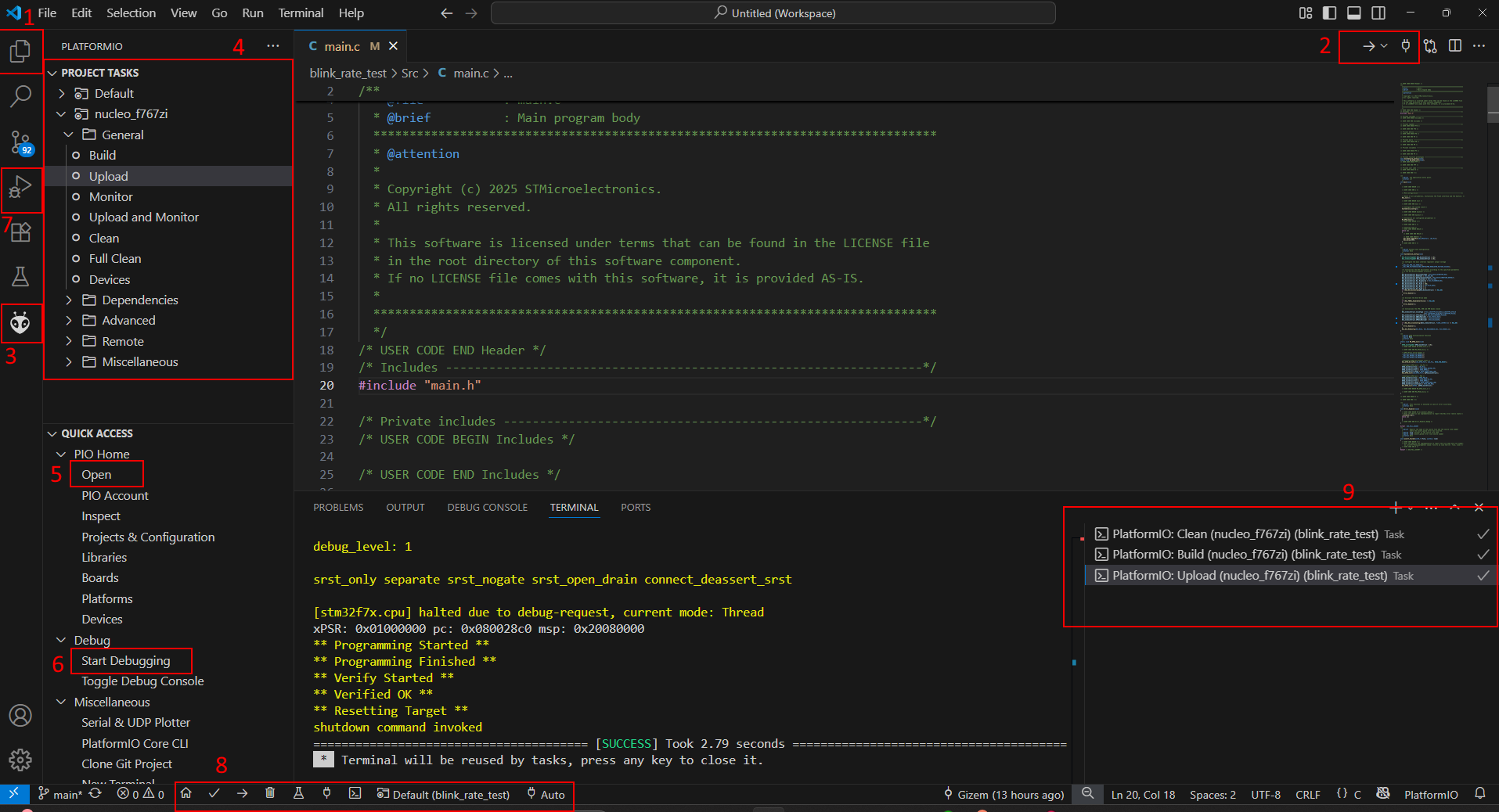
- Here you can see your files; source codes and headers.
- You can build your code, upload it from the selections on the arrow icon. You can also open serial monitor with the socket icon.
- This opens the home of PlatformIO. The left tab will show up (instead of your file explorer) when you click it.
- Another option to build, upload and clean your code. Cleaning in compiled languages mean to delete your built files for you to build again. Sometimes it is very useful!
- To open a new project.
- For debugging
- Alternatively you can change the view into debugging view, which I like better.
- Those are the buttons we use the most. From left to right, 1-PIO Home, 2-build, 3-upload, 4-clean, 5-test(we don’t use it in this course), 6-open serial monitor, 7-open new terminal, 8-which project you are running right now. The last one (Default(project_name)) is so important to keep an eye on. Especially when you switch between projects in the explorer, it is so easy to forget about swithching platformIO setup, too. Make sure that you are working on the right project.
- How many terminals you have opened. Please remember to close unused terminals sometimes…
Datasheet, reference manual, user manual
We chose STM32F767-Nucleo board for its power and efficiency as well as built-in ethernet module. Unfortunately, it is very hard to find a full plan on how to learn on STM32F767-Nucleo board tutorials online - like there are for Arduino. Therefore, you have to learn how to read datasheet, reference and user manuals:
- Datasheet for STM32F767xx link
- Reference manual for STM32F767xx link
- User manual of Nucleo-144 board link
- User manual for STM32F7 HAL and low-layer drivers link
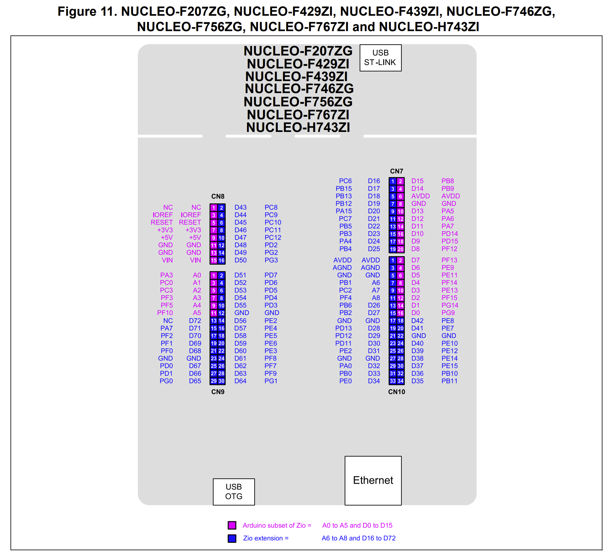
- Board pinout link
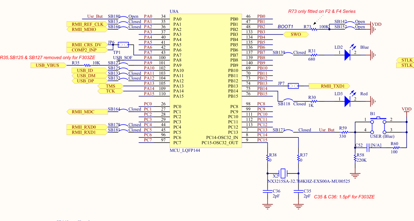
- Nucleo circuit diagram link
While comprehensive tutorials specifically tailored for the STM32F767-Nucleo board are rare, there are many resources available for a variety of other STM32 development boards, such as the Discovery series, the popular “blue pill,” older Nucleo boards, and the L4 series, among others. The good news is that the fundamental concepts of microcontroller programming especially within the STM32 family are largely transferable between different boards. Once you grasp the core ideas, such as pin configuration, peripheral initialization, and the use of the HAL (Hardware Abstraction Layer) or direct register manipulation, adapting code from one STM32 board to another becomes a straightforward process.
For example, tutorials that demonstrate how to blink an LED, set up UART communication, or configure timers on a Discovery or blue pill board can be readily applied to the STM32F767-Nucleo with only minor adjustments, typically related to pin assignments or specific peripheral names. This flexibility is one of the strengths of the STM32 ecosystem, supported by consistent documentation and a unified set of development tools.
Therefore, don’t hesitate to explore tutorials and example projects for other STM32 boards. As you build your understanding of the microcontroller architecture and the STM32 HAL/LL libraries, you’ll find it increasingly easy to port and adapt code, regardless of the specific board in use. This skill will serve you well as you tackle more advanced projects and work with a variety of STM32 hardware in the future.
Some useful links
Exercise-1: Toggle all 3 LEDS
Turn on all three LEDs one by one, and turn them off afterwards.
Steps:
- The name of the 3 pins are:
- LD1, LD2 and LD3
- Start a new STM32CubeMX project. If you select the default mode, the LED assignments will be already done.
- Skip clock configurations (for now).
- Do the necessary changes in the Project Manager tab and generate the source code.
- Create a platformio.ini and Copy the necessary content in it.
- Open the project using PlatformIO home page.
- Do the necessary changes after
/*USER CODE BEGIN 3*/in main.c. - Build and upload.
- Observe the three built-in LEDs.
Exercise-2: Change blink rate
Adjust your code such that your LED blinks faster and slower.
Different frameworks that you can use with STM32F767
You can program your nucleo board using many different languages/frameworks. You can use Arduino framework, LL library, Bare-metal, HAL library and ARM CMSIS. In this course we will use HAL, but it is essential that you know what is available and have an overview why we chose HAL for this course.
(Note: We are using HAL not because it is necessarily superior, but because it offers a good balance between ease of learning, flexibility in configuration, and widespread use. This makes it the most practical choice for this course.)
Note that as long as you include right header files, you can use any library, you can even combine them! However, it is smart to stick only one.
How does Arduino code look like:
#include<Arduino.h>

void setup() {
  // initialize digital pin PB0 as an output.
  pinMode(PB0, OUTPUT);
}
// the loop function runs over and over again forever
void loop() {
  digitalWrite(PB0, HIGH);   // turn the LED on (HIGH is the voltage level)
  delay(500);              // wait for a second
  digitalWrite(PB0, LOW);    // turn the LED off by making the voltage LOW
  delay(500);              // wait for a second
}
How does LL-library code look like:
/* Includes ------------------------------------------------------------------*/
#include "stm32f7xx_ll_bus.h"   // Required for clock enabling
#include "stm32f7xx_ll_gpio.h"  // Required for GPIO configuration and control
#include "stm32f7xx_ll_utils.h" // Required for LL_mDelay function

int main(void)
{
   LL_APB2_GRP1_EnableClock(LL_APB2_GRP1_PERIPH_SYSCFG);
   LL_APB1_GRP1_EnableClock(LL_APB1_GRP1_PERIPH_PWR);
   NVIC_SetPriorityGrouping(NVIC_PRIORITYGROUP_4);
   SystemClock_Config();
   MX_GPIO_Init();
   MX_USART2_UART_Init();
   while (1)
   {
      LL_GPIO_TogglePin(LD3_GPIO_Port, LD3_Pin);
      LL_mDelay(1000);
   }
}
How Bare-metal look like:
/* Define base addresses for relevant peripheral registers */
#define RCC_BASE            0x40023800UL    // Reset and Clock Control (RCC) base address
#define GPIOB_BASE          0x40020400UL    // GPIO Port B base address

/* RCC Register Offsets */
#define RCC_AHB1ENR_OFFSET  0x30UL          // AHB1 Peripheral Clock Enable Register

/* GPIOB Register Offsets */
#define GPIOB_MODER_OFFSET  0x00UL          // GPIO Port Mode Register
#define GPIOB_ODR_OFFSET    0x14UL          // GPIO Port Output Data Register
#define GPIOB_OSPEEDR_OFFSET 0x08UL         // GPIO Port Output Speed Register
#define GPIOB_PUPDR_OFFSET  0x0CUL          // GPIO Port Pull-up/Pull-down Register

void main(void)
{
   RCC_APB2ENR |= RCC_IOPCEN;
   GPIOC_CRH   &= 0xFF0FFFFF;
   GPIOC_CRH   |= 0x00200000;
   while(1)
   {
      GPIOC_ODR |=  GPIOC13;
      for (int i = 0; i < 500000; i++); // arbitrary delay
      GPIOC_ODR &= ~GPIOC13;
      for (int i = 0; i < 500000; i++); // arbitrary delay
   }
}
How ARM CMSIS look like:
#define STM32F411xE
#include "stm32f7xx.h"

void __attribute__((optimize("O0"))) delay (uint32_t time)
{
   static uint32_t i;
   for (i=0; i<time; i++) {}
}

int main (void)
{
   RCC->AHB1ENR     |= RCC_AHB1ENR_GPIOCEN; //RCC ON
   GPIOC->MODER    |= GPIO_MODER_MODER13_0; //mode out
   GPIOC->OTYPER   = 0;
   GPIOC->OSPEEDR  = 0;

   while (1)
   {
      GPIOC->ODR ^=   GPIO_ODR_OD13;
      delay(1000000);
   }
}
HAL library and registers
pass