Lecture 3 - Timers and Interrupt
Peikarar forts. Timing og avbrudd.
Register reading
pass
Bit masking
pass
typedef, struct, union
pass
CLOCK
Undeniably the most important thing in a digital system. Therefore, it is fundamental to understand the concept of clock, to understand how an embedded system works.
Why clock is everything?video
In STM32 microcontrollers, SYSCLK (System Clock) is the main clock source for the entire system, while HCLK (AHB Clock) is a derived clock used by the CPU and AHB bus. SYSCLK can be generated from various sources like HSI, HSE, or PLL, and then HCLK is derived from SYSCLK by a configurable prescaler. This means that HCLK runs at a lower frequency than SYSCLK, and it is used to clock the core and other AHB peripherals.
SYSCLK: This is the main clock for the STM32 microcontroller. It’s the output of the clock multiplexer and can be sourced from the internal high-speed oscillator (HSI), the external high-speed oscillator (HSE), or the PLL (Phase-Locked Loop). The SYSCLK frequency is often the highest frequency the microcontroller can operate at. HCLK: This clock is derived from SYSCLK and is typically used to clock the CPU core, the AHB bus, and some AHB peripherals. The HCLK frequency is often lower than the SYSCLK frequency because it’s often divided down from the SYSCLK using a prescaler. This division helps to optimize power consumption and allows different peripherals to operate at different clock speeds. Relationship: The SYSCLK is the source for the HCLK. A prescaler, configured in the RCC (Reset and Clock Control) registers, divides the SYSCLK to produce the HCLK. For example, if SYSCLK is 100 MHz and the prescaler is set to divide by 2, then HCLK will be 50 MHz. Usage: SYSCLK is used to clock the core and the AHB bus. HCLK is used to clock the CPU core and other AHB peripherals. Some peripherals, like those connected to the APB buses (APB1 and APB2), may have their own dedicated clocks derived from HCLK using additional prescalers.
No prinft, yes debugging
pass
Activate debugger in platformio.ini file:
[env:nucleo_f767zi]
platform = ststm32
board = nucleo_f767zi
framework = stm32cube
upload_protocol = stlink
debug_tool = stlink
build_flags =
    -IInc

; --- Full SWO Configuration ---
debug_server =
    ${platformio.packages_dir}/tool-openocd/bin/openocd.exe
    -f interface/stlink.cfg
    -f target/stm32f7x.cfg
Which timer is used
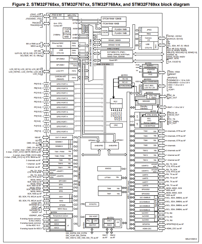
Let’s look at the block diagram of our microcontroller in the datasheet. In Figure 2 on page 20, you can see how the pins are connected:
LED blink with correct clock settings
RCC In the previous exercises, we haven’t done anything with the clock settings. Our code worked just fine but it is time to stop “default settings”. As you remember the blink rate is a bit slower than 500ms, right? It is because we haven’t configured the clock settings properly and we have lots of pins configured by default even if we don’t use. We will fix the blink rate issue NOW!.
- Open a new STM32CubeMX project.
- Select STM32F767 board, start project, but DO NOT SELECT default mode.
- You should see some pins are orange. We want these to be gone, as well:
Pinout (at the top) > Clear pinouts - Set PB0 as GPIO_Output.
- On the left
System Core > RCC > HSE: Crystal/Ceramic Resonator - Master Clock Output: Checked.
- On the left
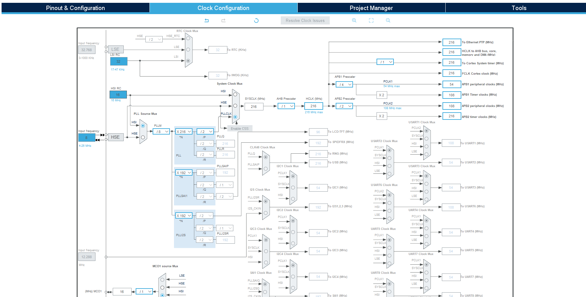
System Core > GPIO > Configuration > PB0 >Change user label toLD1 - Go to Clock Configuration. Set these values:
- Go to Project Manager a. Give descriptive name to your project b. Application structure: Basic c. Toolchain/IDE: STM32CubeIDE (Uncheck “Generate under root” box)
- Generate project.
- Copy platformio.ini file from your prior projects.
- Open the project in PlatformIO.
- Add this code after
/*USER CODE BEGIN 3*/in main.c:HAL_GPIO_TogglePin(LD1_GPIO_Port, LD1_Pin); HAL_Delay(500); - Build and Upload