Lecture 4 - Timers and Interrupt 2
Some important C concepts
In this course, we are using the HAL (Hardware Abstraction Layer) libraries provided by STMicroelectronics for STM32 microcontrollers. They are high-level, user-friendly interface to the hardware features of the microcontroller. Instead of writing low-level code to directly manipulate hardware registers (which can be error-prone and difficult to maintain), the HAL provides functions that abstract away the hardware details. This makes your code more portable, easier to read, and less dependent on the specific microcontroller model. They are often sufficient for many of the projets but sometimes, we might need small modifications on our registers.
If you look at stm32f7xx_hal_gpio.h or other HAL library headers, you will see that all HAL functions are intrinsically do some register manipulations.
Even though HAL is written in C, you can use it in C++ projects as well. C++ is fully compatible with C, but you need to tell the C++ compiler that the HAL functions have C linkage. This is done using the extern "C" keyword in your code. For example, in your C++ source file:
Binary operations
The Basics: Bits, Bytes, and Hexadecimal
Before we start, let’s quickly review the building blocks:
- Bit: The smallest unit of data, either a 0 or a 1.
- Byte: A group of 8 bits.
- Nibble: A group of 4 bits (half a byte).
- Word: The natural unit of data used by a particular processor. For the STM32F767 (a 32-bit microcontroller), a word is typically 32 bits (4 bytes).
- Hexadecimal (Hex): A base-16 number system often used to represent binary data concisely. Each hexadecimal digit represents 4 bits. You will frequently see hexadecimal numbers when dealing with STM32F767 registers (e.g., GPIOA->ODR = 0x01;). It’s much more readable than a long string of binary digits.
Addition, subtraction and compliment
Adding two 4-bit numbers:
  0101 (5 in decimal)
+ 0011 (3 in decimal)
------
  1000 (8 in decimal)
Subtracting two 4-bit numbers:
  1010 (10 in decimal)
- 0011 (3 in decimal)
------
  0111 (7 in decimal)
1’s compliment: Convert the bit to its opposite.
Number: 0101
One's Complement: 1010
2’s compliment: Two’s complement is the most common method for representing signed integers in computers, including the STM32F767. To find the two’s complement:
- Find the one’s complement.
- Add 1 to the one’s complement.
Example: Find the two’s complement of 0101 (positive 5):
1. One's complement: 1010
2. Add 1: 1010 + 1 = 1011
So, 1011 represents -5 in a 4-bit two’s complement system.
Bitshift operators
Left Shift («) Shifts bits to the left, filling vacant positions with 0s. Each left shift is equivalent to multiplying by 2.
Example: 0001 << 2
0001 (1 decimal)
0010 (2 decimal, after 1st shift)
0100 (4 decimal, after 2nd shift)
We use left shift operator when we create bit masks:
// Enable clock for GPIOA in the RCC AHB1ENR register
// GPIOAEN is bit 0 in AHB1ENR
RCC->AHB1ENR |= (1 << 0);
One can also use left shift to multiply a number by 2:
uint32_t value = 10;
value = value << 2; // value becomes 40 (10 * 2^2)
Right Shift (») Shifts bits to the right. For unsigned numbers, 0s are typically shifted in from the left. For signed numbers, the sign bit is usually replicated (arithmetic right shift) to preserve the sign.
Example: 0100 >> 2
0100 (4 decimal)
0010 (2 decimal, after 1st shift)
0001 (1 decimal, after 2nd shift)
We use right shift to extract bit fields, but it is not as often used as left shift:
// Assuming a 32-bit register where bits 8-10 represent a value
uint32_t register_value = some_register;
uint32_t extracted_value = (register_value >> 8) & 0x07; // 0x07 is 0b111 mask for 3 bits
One can also use right shift to divide a number by 2:
uint32_t value = 40;
value = value >> 2; // value becomes 10 (40 / 2^2)
Binary operators
Bitwise AND(&)
AND operator is the same as you know from introduction to programming and/or digital electronic courses. However in microcontrollers AND operator has two particular usages: Clearing a specific bit and checking if a pin is set.
First remember the truth table of AND: Here is the truth table for the AND operator:
| A | B | A & B |
|---|---|---|
| 0 | 0 | 0 |
| 0 | 1 | 0 |
| 1 | 0 | 0 |
| 1 | 1 | 1 |
The result is only 1 if both A and B are 1; otherwise, the result is 0.
How do we clear bits using AND operator? We use & with a mask to clear (set to 0) specific bits while leaving others unchanged: REG &= ~(1 << bit_position)
// Clear bit 0 (PA0) of GPIOA->ODR register
// To turn off an LED connected to PA0
GPIOA->ODR &= ~(1 << 0); // (1 << 0) creates 0b000...0001
                         // ~(1 << 0) creates 0b111...1110 (all bits set except bit 0)
How do we check id a bit is set?
// Check if bit 5 (PA5) of GPIOA->IDR register is set
if (GPIOA->IDR & (1 << 5)) {
    // PA5 is high
}
Bitwise OR(|)
OR operator is the same as you know from introduction to programming and/or digital electronic courses. However in microcontrollers OR operator has a particular usage: Setting a specific bit and checking if a pin is set.
First remember the truth table of AND: Here is the truth table for the AND operator:
| A | B | A | B |
|---|---|---|
| 0 | 0 | 0 |
| 0 | 1 | 1 |
| 1 | 0 | 1 |
| 1 | 1 | 1 |
The result is 1 if either A or B is 1; otherwise, the result is 0.
We use | with a mask to set (set to 1) specific bits while leaving others unchanged: REG |= (1 << bit_position)
// Set bit 0 (PA0) of GPIOA->ODR register
// To turn on an LED connected to PA0
GPIOA->ODR |= (1 << 0); // (1 << 0) creates 0b000...0001
So by using OR and AND operators, we manipulate registers:
// Configure PA5 as output (assuming MODER is a 2-bit field)
// MODER5[1:0] = 01 (General purpose output mode)
// This example is simplified; actual register manipulation involves masks.
GPIOA->MODER |= (1 << (5 * 2)); // Sets MODER5[0]
GPIOA->MODER &= ~(1 << (5 * 2 + 1)); // Clears MODER5[1]
Bitwise XOR(^)
The bitwise XOR (exclusive OR) operator returns 1 if the corresponding bits are different. Here is the truth table for the XOR (exclusive OR) operator:
| A | B | A ^ B |
|---|---|---|
| 0 | 0 | 0 |
| 0 | 1 | 1 |
| 1 | 0 | 1 |
| 1 | 1 | 0 |
The result is 1 if A and B are different; otherwise, the result is 0.
In microcontrollers, we use XOR to toggle a bit.
// Toggle bit 0 (PA0) of GPIOA->ODR register
// To blink an LED connected to PA0
GPIOA->ODR ^= (1 << 0);
External Interrupts
TODO definition Debugging, reading register value using platformIO. https://ele102.gitlab.io/automatisering-frde/ele102-frde/texts/Lessons/L7_timer_interrupt.html#external-interrupts
Interrupts are in the core of our PCs. All keyboard press, mouse input etc, are all handled with exceptions. See this website for more: https://www.cs.emory.edu/~cheung/Courses/355/Syllabus/6-io/0-External/interupt.html
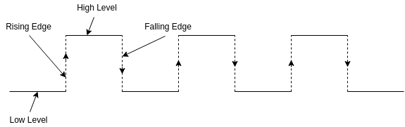
Edge detection
When reading a digital input it is often desirable to determine the instant it is changing, and how it is changing. I.e. whether it is a rising, or a falling edge. There are several approaches we can take to solve this problem, but in this section we focus on solutions involving the sampling of the digital input. I.e. we are continuously checking the state of the digital input with a certain time interval. This approach is fine for slowly changing signals such as push buttons. Actually it is not only fine, it is often the recommended way to deal with slow signals.
In order to detect the rising edge of a digital input by the sampling method, we continuously compare the current state of the input, to the state at the previous iteration (the previous time we checked it). If the previous value was low, and the current value is high, we have a rising edge. The same logic can be applied it the reverse direction to detect the falling edge.
The following pseudocode illustrates the typical way one detects a rising edge in software:
if(button_state != button_previous_state){
    // Code to execute when the state of the button changes can be placed here

    if(button_state == PRESSED){
        // Code to execute on rising edge can be placed here
        // I.e. state has both changed and is high, this can
        // only happen if the state used to be low, and just
        // became high. In other words it must be a rising edge.l
    }
}
Understanding Pull-up/ Pull-down resistors
Let’s think about what happens when you press a button.
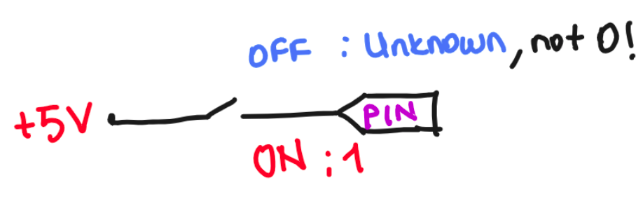
As already discussed in terms of push buttons, when using digital inputs it is often required to add resistors to either pull up, or pull down the potential at the input. This is required because the input impedance of the digital input is very high, and the state may change randomly if it is not forced to a known state. For our convenience the STM32CubeMX allows us easy configuration. Alternatively you may add external resistors.
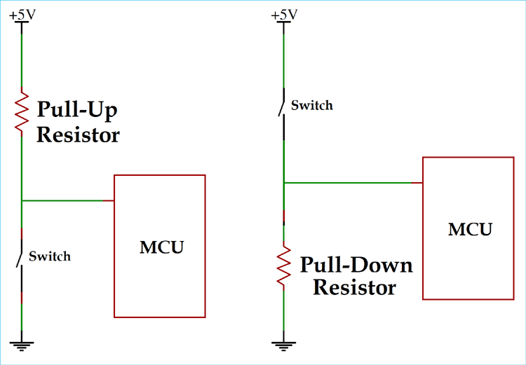
The size of the resistors is not critical, but it should not be selected on random either. A to small resistor may cause excessive current, while a to large resistor will defeat the purpose of trying to pull towards a given potential. I.e. the resistor value should be far away from the value of the input impedance. In practice a 10k resistor is often used, but both 5k and 50k will also work.
 Source: circuitdigest.com
The following figure depicts the connection of two push buttons to the Arduino (another development board but the concept is the same). For the leftmost button the resistor in the figure pulls the input low, and the push button is connected in such a way that it can pull it up. For the button to the right the configuration is opposite.

It is very important to realize that the default state of a digital input depends on whether the input is pulled up, or pulled down. If the input is pulled down by a resistor, and the push button pulls it up, then a push on the button will make the input logical HIGH. If on the other hand the input is pulled up by a resistor, and a push on the button pulls it down, pushing the button will make the input logical LOW
It is not important which of the two you choose, because it is easy to invert the state in software. But it is important to realize the difference, in order to know when you have to invert it in software.
Exercise: Bounce problem with external interrupts
- Open a new STM32CubeMX project.
- Select STM32F767 board, start project, but DO NOT SELECT default mode.
- You should see some pins are orange. We want these to be gone, as well:
Pinout (at the top) > Clear pinouts - Set PC13 as
GPIO_EXTI13and leave the first two configurations unchanged, but rename the pin toUSER_BTN. This is the pin to which our user button connected. Alternatively, you can select another pin where your external button is connected.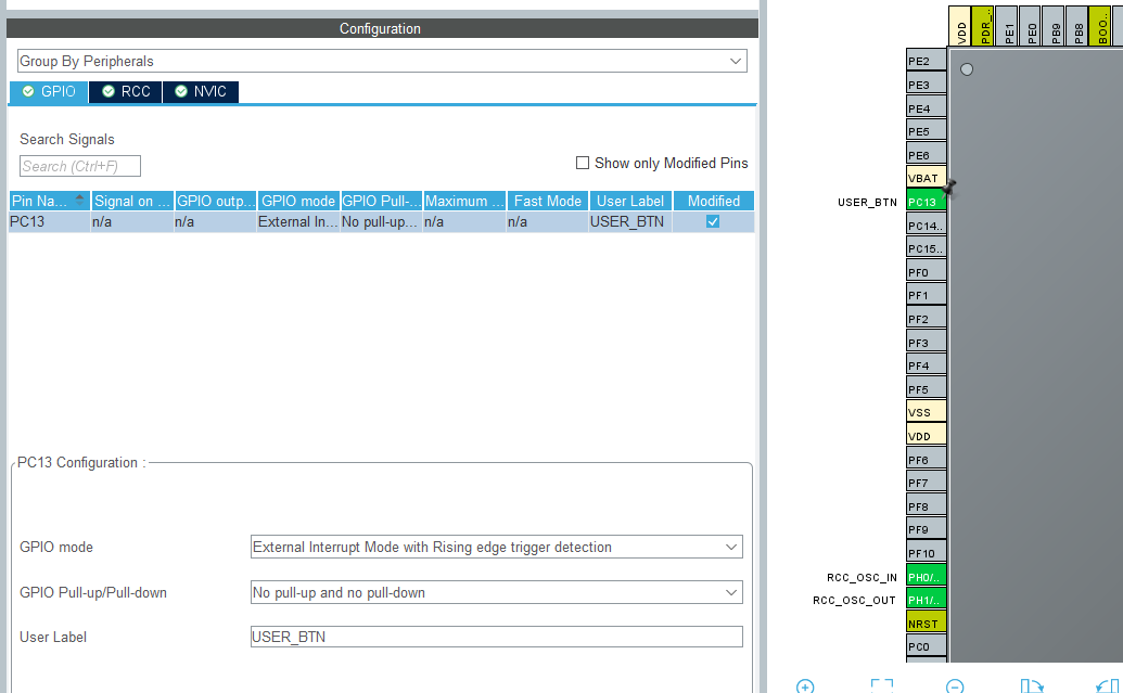
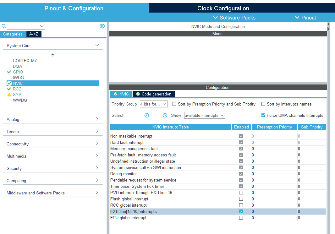
- Open The NVIC Tab And Enable The EXTI line 13 interrupt. This is where we adjust the priorities of multiple ISRs.
- Set PB0 as
GPIO_Output. - On the left
System Core > GPIO > Configuration > PB0 >Change user label toLD1 - On the left
System Core > RCC > HSE: Crystal/Ceramic Resonator(RCC: Reset and Clock Control) - Master Clock Output: Checked. (only for a possible debugging)
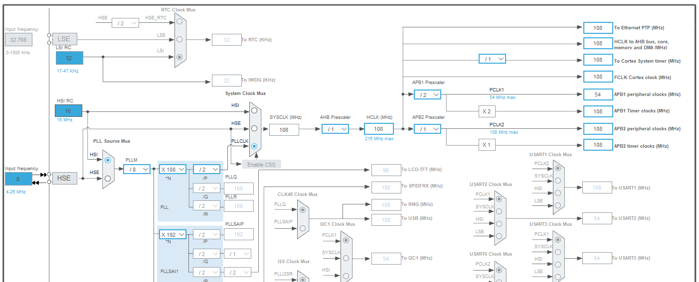
- Go to Clock Configuration. Set these values:
- Create a platformio.ini file and copy these in it:
[env:nucleo_f767zi]
platform = ststm32
board = nucleo_f767zi
framework = stm32cube
build_flags =
 -IInc
upload_protocol = stlink
debug_tool = stlink
debug_build_flags = -O0 -g -ggdb
Now we are done with the setup. It is time to modify the code. What we want is to toggle LD1 as we press the USER_BTN. Before implementing anything, let’s analyze the generated code.
At the end of stm32f7xx_it.c, you will see that a new function is generated for us: EXTI15_10_IRQHandler(). This function handles external interrupts for lines 10 to 15. We call call it as “entry points for interrupts on EXTI lines 10-15. This function’s address is stored in the microcontroller’s interrupt vector table. When an interrupt occurs on any of EXTI lines 10-15, the CPU will automatically jump to this function to handle it. Our USER_BTN pin was PC13. So far so good.
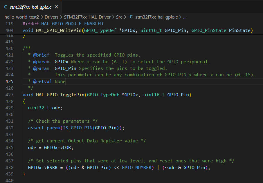
There is one line of code in this function and it is just a function call for HAL_GPIO_EXTI_IRQHandler(). This is a raw interrupt handler. Raw handlers, which are often weakly defined in the HAL library’s source files (e.g., stm32f4xx_it.c), then call HAL_GPIO_EXTI_IRQHandler() and pass the specific GPIO_Pin that caused the interrupt.
If you go into HAL_GPIO_EXTI_IRQHandler(), you will see what that there is some code inside in this function. The critical line for us is HAL_GPIO_EXTI_Callback(). The definition is a weak function definition __weak void HAL_GPIO_EXTI_Callback(uint16_t GPIO_Pin), which means that it can be overwritten. In other words weak function definitions provide default, overridable implementations. However, it is located under Drivers > STM32F7xx_HAL_Driver > Src > stm32f7xx_hal_gpio.c. This path is in the core or the HAL libraries and we DON’T WANT TO MODIFY THEM!
What we can to is that, if we define a HAL_GPIO_EXTI_Callback(uint16_t GPIO_Pin) function in our main.c, we overwrite the functionality of its weak definition. Therefore, we won’t be changing the core drivers, keep our code tidy, since our interrupt vector already calling a `HAL_GPIO_EXTI_Callback().
- Place this code after
/* USER CODE BEGIN 4 */in yourmain.c:void HAL_GPIO_EXTI_Callback(uint16_t GPIO_Pin){ if(GPIO_Pin == GPIO_PIN_13){ // Check whether the interrupt source is EXTI Line13 (PC13 Pin) HAL_GPIO_TogglePin(LD1_GPIO_Port, LD1_Pin); // Toggle LD1 } } - Build and upload the code.
- Observe
LD1as you press the
How does it work?
One might think that we haven’t written anything inside int main(). We haven’t checked if USER_BTN is SET or RESET. How does it work?
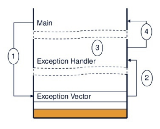
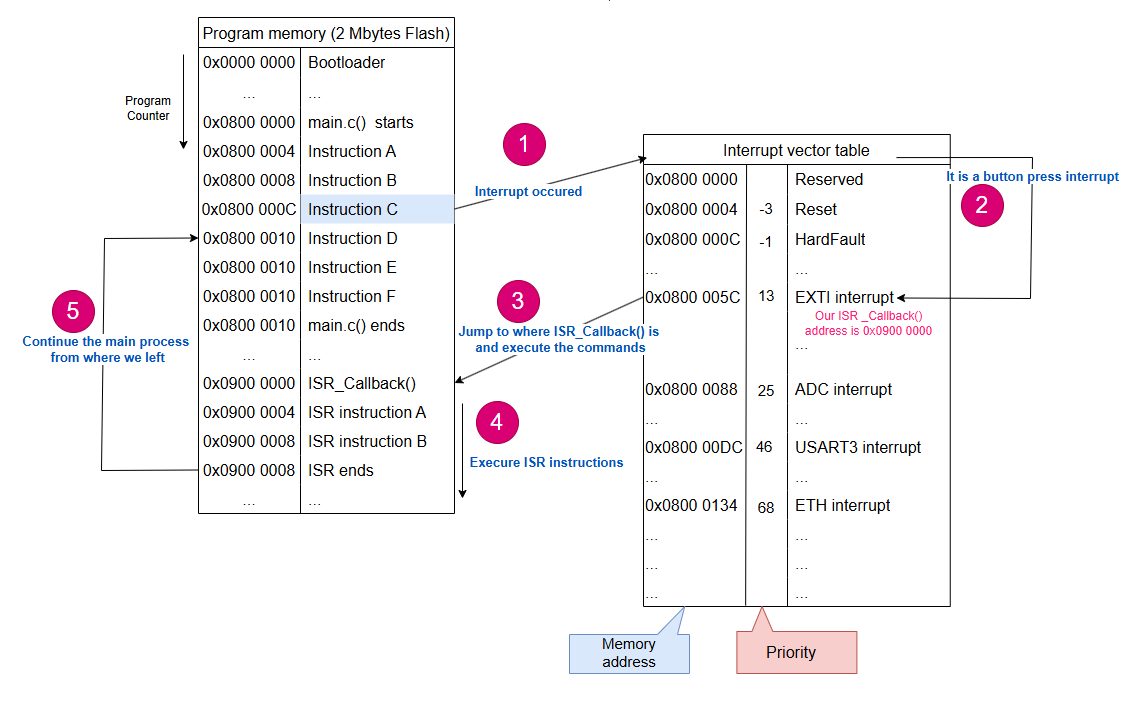
Well, this is my friend, the magic of ISR. As you define an interrupt, your ISR handler know that if the interrupt event occurs, an exception will occur and your program counter will jump directly where your interrupt callback function is defined in the memory. It will run and complete it unless another interrupt occurs, and jump back to main.c. Since we don’t have anything in our main function, there is not much to do there in this exercise. The process look like this:
 Source: deepbluembedded.com
- When an exception occurs, the current instruction stream is stopped and the processor accesses the exceptions vector table.
- The vector address of that exception is loaded from the vector table.
- The exception handler starts to be executed in handler mode.
- The exception handler returns back to main (assuming no further nesting).
Please check this link to learn more in depth about how interrupts work. It is extensive and not all are in the scope of this course, but very nicely explained.
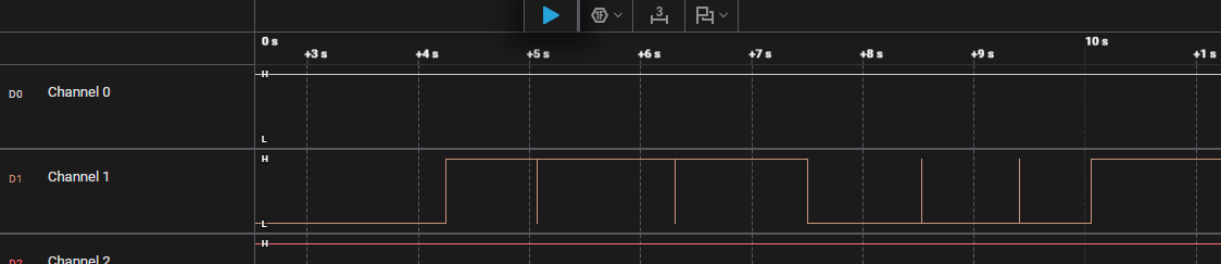
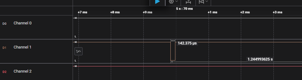
Why it is not reliable?
Because of debouncing! If you look at the logic analyzer you will see some of the presses are registered twice or triple. If we zoom in, we see a jutter around 140 us.
Debouncing
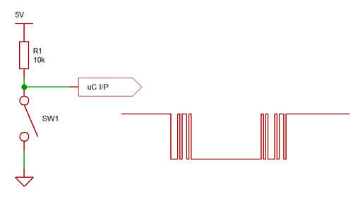
A mechanical switch will often generate spurious open/close transitions in a short period after it has been activated. It is a risk that these spurious transitions are interpreted as multiple signals from the switch. In order to avoid these problems some form of debounce remedy should be applied. This could be a hardware solution, a software solution or a combination of the two.
The graph to the right in the following figure illustrates the spurious changes in voltage level at the node between the resistor and the switch.
Hardware debounce methods
Hardware solutions include analog filters using resistors and capacitors, or digital circuits. The simplest one is probably applying a low-pass filter at the output:
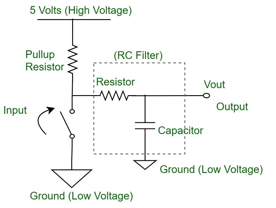 Source: www.geeksforgeeks.org
A low-pass filter is designed to pass low-frequency signals (like the intended steady voltage from the switch) while attenuating high-frequency signals (like the bouncing noise).
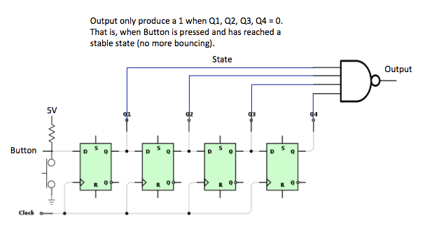
Another alternative is clocking the button state in to the d flip-flops, and only when all the flip-flops have registered the same state the output will change. This solution is typically found in programmable logic, but it is rather expensive to realise by using discrete components.
 Source: e-thinkers.com
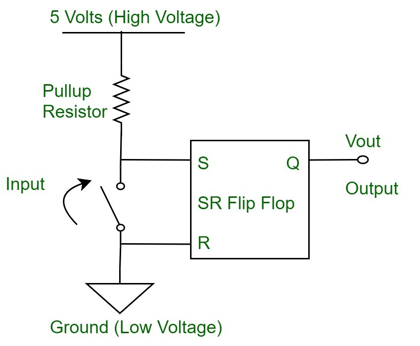
A really efficient and reliable debounce circuit can be built bu using a SR-latch in conjunction with a SPDT switch. In one position the switch is connected to the set input, while the other position of the switch is connected to reset input of the latch. That way you do not have to consider the time you expect the bouncing to last, or the duration between each of the spurious voltage pulses.
 Source: www.geeksforgeeks.org
Software debounce methods
If a software debounce solution is desired, one possibility is to check the button state twice, within a short time windows. I.e. check, delay, check again. The following source code listing illustrates one possibility:
Note that the variables are declared static inside the loop() function. This ensures that the value is persistent between the invocation of the function. Alternatively they could be declared globally, i.e. outside of any function definition.
Exercise: Software debouncing
Software debouncing is an algorithm to filter out the rapid, unwanted changes (bounces) in a button’s signal caused by its mechanical contacts. It typically involves checking the button state multiple times over a short period and only accepting a change if the state remains stable, ensuring that only intentional presses are registered.
We can modify our previous code and implement a software debouncer:
- Paste this code after
/* USER CODE BEGIN PV */:// --- Global Variables for Debouncing --- volatile uint32_t lastDebounceTime = 0; const uint32_t debounceDelay = 10; // 10 milliseconds - Modify your interrupt callback after
/* USER CODE BEGIN 4 */:void HAL_GPIO_EXTI_Callback(uint16_t GPIO_Pin){ if (GPIO_Pin == GPIO_PIN_13){ // Get the current tick time uint32_t currentTime = HAL_GetTick(); // Check if enough time has passed since the last valid press if ((currentTime - lastDebounceTime) > debounceDelay){ // If yes, this is a valid button press/release HAL_GPIO_TogglePin(LD1_GPIO_Port, LD1_Pin); // Update the last debounce time lastDebounceTime = currentTime; } // If not enough time has passed, ignore this interrupt (it's bounce) } }
Observe that it it not perfect, but much better :) You can adjust the delay duration for better results.
Pay attention that HAL_GetTick() function gives you the current time in milliseconds after HAL_Init() is called. Therefore, our debouncer ignores any second changes within 10 ms after the first press detected.
ISR
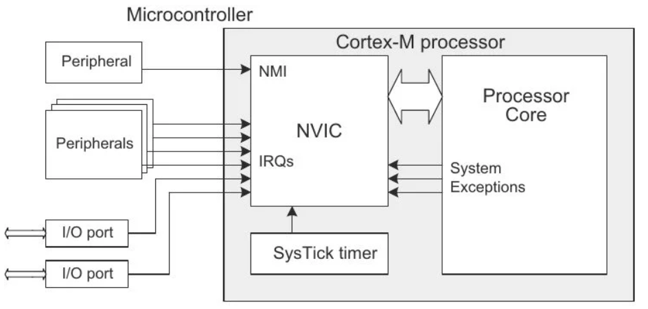
Each microcontroller company offers a procedure to handle multiple exceptions. Arm® Cortex®-M7 microcontrollers are great in handling exceptions and interrupts. They offer some the Nested Vectored Interrupt Controller (NVIC). This is what we played with in CubeMX when we were setting our external interrupt exercise.
NVIC is responsible for managing all the interrupts and exceptions in the system, ensuring they are handled efficiently and in the correct order based on their assigned priorities.
 Source: microcontrollerslab.com
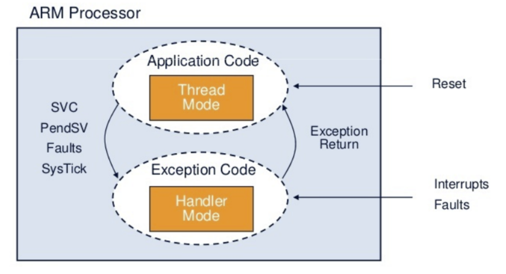
The processor mode can change when exceptions occur. And it can be in one of the following modes:
- Thread Mode: Entered on reset.
- Handler Mode: Entered on all other exceptions.
 Source: deepbluembedded.com
Those exceptions can be internal (from timers, ADC, PWM) or external (from swithces or communication protocols).
Inherently, there are many exceptions are implemented in a project. Interrupt vector handles execution of those interrupts. In reference manual, you can see all the interrupts and their default priority.
Key Considerations in interrupt usage
- Keep ISRs Short and Fast: This is the most crucial rule for any interrupt handler. Avoid:
- Long delays (e.g.,
HAL_Delay()). - Complex calculations.
- Blocking operations (e.g., waiting for peripherals).
- Printing to serial (e.g.,
printf) if it’s blocking. - If you have extensive work to do, set a flag in the ISR and handle the work in your main loop or a dedicated task (if using an RTOS).
- Long delays (e.g.,
- Debouncing: Buttons are mechanical and create electrical noise (bouncing) when pressed/released. Without debouncing, a single button press can trigger multiple interrupts. Implement either:
- Hardware debouncing (RC circuit), or
- Software debouncing (like the example above, or a more robust state machine).
- Volatile Keyword: If you use a global variable (like
last_button_press_timeorbutton_pressed_flag) that is modified inside an ISR and read elsewhere (e.g., inmain), declare it asvolatile. This tells the compiler not to optimize away reads/writes, ensuring the latest value is always used. - Interrupt Priority: In STM32CubeMX, configure the NVIC (Nested Vectored Interrupt Controller) priority for your EXTI line. Higher priority interrupts can preempt lower priority ones.
- Re-entrancy: Be careful if your ISR modifies variables that are also accessed by the main loop or other ISRs. Use appropriate synchronization mechanisms (like briefly disabling interrupts, or using RTOS semaphores/mutexes) if necessary, but generally, keep it simple for GPIO toggling.
Exercise (Home/Lab): Button press counter
Create a simple project where every time you press a button (connected to an external interrupt pin), a counter increases and debug your counter variable.
Exercise: Interrupt counter
Let’s make a counter using our interrupt. This time, instead of counting the number of button presses, we would like to measure the duration of the button press. As long as your button is pressed, the counter will increase, as soon as you release the button, the counter will stop counting.
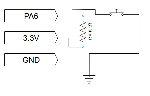
Set up button circuit with a pull-up resistor like so:
For this task, we can use Gated mode, which was mentioned in Lesson 3.
- Open a new STM32CubeMX project.
- Select STM32F767 board, start project, but DO NOT SELECT default mode.
- You should see some pins are orange. We want these to be gone, as well:
Pinout (at the top) > Clear pinouts - First set the clock On the left
System Core > RCC > HSE: Crystal/Ceramic Resonator(RCC: Reset and Clock Control) - Master Clock Output: Checked. (only for a possible debugging)
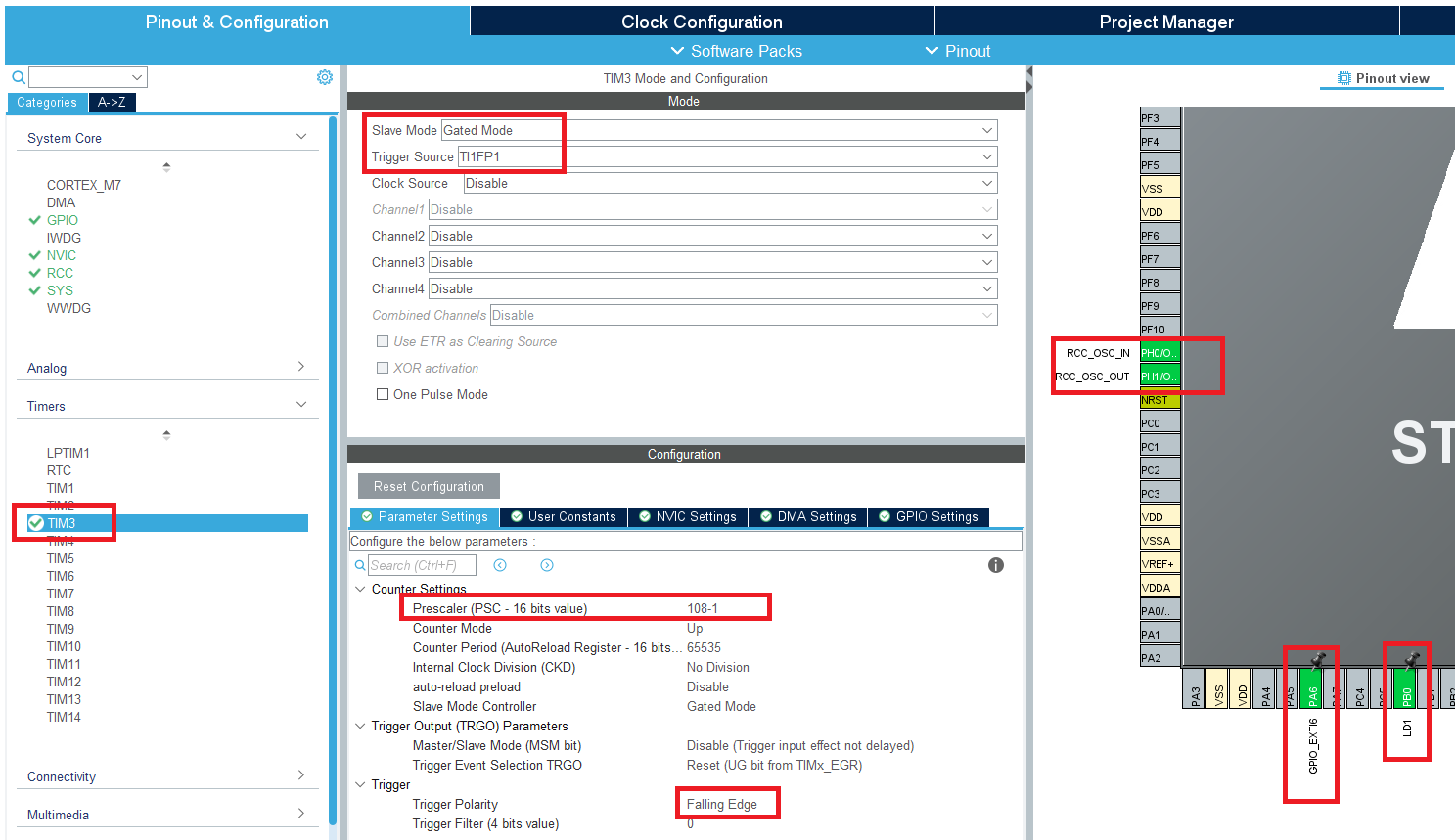
- This time we can use TIM3, just because our heart desires so, and set its slave mode Gated Mode.
- Since we want the timer to be triggered by an external input, we will choose the trigger mode TI1FP1. This will enable
PA6for us. - As before, we set the prescalar to 108-1 so that each tick will be 1 us for this timer.
- Since we have a pull-up resistor on our button, the default state of
PA6will beSET. When we press the button, the signal will be low. Therefore, we must select “Falling Edge” as trigger polarity. If we had a pull-down resistor, then we would have chosen “Rising Edge”. - Enable the TIM3 global interrupt in TIM3’s NVIC settings.
- Also set LD1 on pin
PB0just for debugging later on. - The Pinout should look like this:
- In clock configuration, set the clock as before: 8 MHz input and 108 MHz HCLK.
- Give a proper name, do the necessary changes and generate the code.
- Create a platformio.ini file and copy these in it:
[env:nucleo_f767zi] platform = ststm32 board = nucleo_f767zi framework = stm32cube build_flags = -IInc upload_protocol = stlink debug_tool = stlink debug_build_flags = -O0 -g -ggdb - We would like to see the timer counter value. Therefore let’s create a variable for that after
/* USER CODE BEGIN 0 */.volatile uint16_t tim3_cnt; - Start the timer after
/* USER CODE BEGIN 2 */.// We replace this now // It was just starting the timer counter. // HAL_TIM_Base_Start(&htim3); //But we need this one. // It starts the timer counter and enables the update interrupt (if configured) HAL_TIM_Base_Start_IT(&htim3); - Store the TIM3’s counter value in our variable after
/* USER CODE BEGIN 3 */.tim3_cnt = TIM3->CNT; - And finally add this line in your
MX_TIM3_Init()after/* USER CODE BEGIN TIM3_Init 2 */. This tells the timer to generate an interrupt request to the NVIC whenever a trigger event occurs.__HAL_TIM_ENABLE_IT(&htim3, TIM_IT_TRIGGER); - Build and upload.
- To debug if you timer interrupt work, we have set LD1 to toggle inside the ISR callback function. Observe the LD1 as you press and hold the external button. If so, your interrupt is set properly. Blinking a LED is a very common way to debug in embedded system development since printing a log is much more difficult.
-
Debug the code and see the
tim3_cntupdates as you press and hold the button, and keeps the same value when you release it.You can also observe directly the register value under the register tab in the debugger. Check
TIM3->CNT.
Exercise (Home/Lab): Tilt sensor with LED blink
Make a project that your where you will blink two LEDs: one green one red. Additionally you will have a tilt sensor. As the project stays horizontal, a only green LED will blink at 2 Hz. As the project tilted, the only red LED will blink at 5 Hz.
- You should figure our which pin numbers are connected to green and red LEDs using user manual. Alternatively, you can connect external LEDs.
- You should choose an input pin as GPIO_Input for the tilt sensor.
- Make sure the clock calculations are correct and you get desired blink frequencies.