Exam Cheatsheet
In this page, you will find formulas, diagrams and codes to help you in the exam.
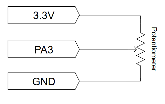
ADC/DAC related calculations
The analog input or output range is determined by a reference voltage, \(V_{ref}\). Typically for an N-bit converter with unsigned digital I/O and unipolar analog range \((0V .. +V_{ref})\), one step at the analog end, \(\Delta V_{LSB}\), is given by:
\[\Delta V_{LSB} = \frac{V_{ref}}{2^N}\]where LSB stands for Least Significant Bit. Similarly for a bipolar analog range \((-V_{ref} .. +V_{ref})\), one step at the analog end is:
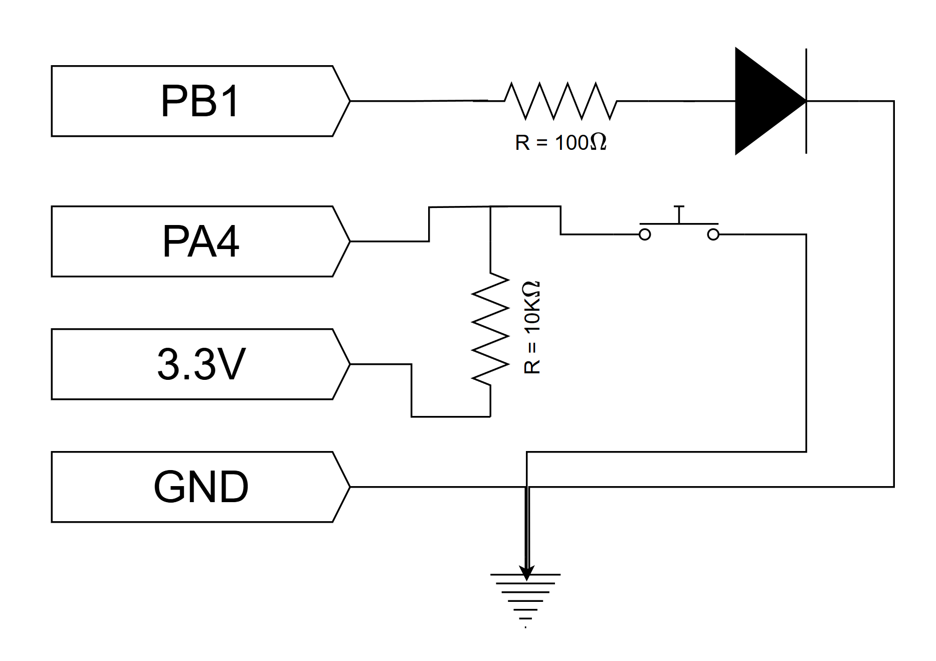
\[\Delta V_{LSB} = \frac{V_{ref+} - V_{ref-}}{2^N}\]To calculate the appropriate resistor value, use the formula:
\[R = \frac{V_{supply} - V_{LED}}{I_{LED}}\]Where:
- \(V_{supply}\) is the supply voltage (e.g., 3.3V from the Nucleo board)
- \(V_{LED}\) is the forward voltage of your LED (from the table above)
- \(I_{LED}\) is the desired current through the LED (typically 10–20 mA for standard LEDs)
Example calculation for a red LED (which has 1.8-2.2V typical voltage range):
- \(V_{supply} = 3.3V\) (from the microcontroller)
- \(V_{LED} = 2.0V\) (typical for red)
- \(I_{LED} = 0.015A\) (15 mA)
Duty cycle and frequency
\[\text{DutyCycle} = \frac{T_{ON}}{T_{ON}+{T_{OFF}}} \times 100\]Frequency is the opposite of periode:
\[f_{PWM} = \frac{1}{\text{Periode}}Hz\]The PWM frequency is calculated like this based on PSC and ARR:
\[f_{PWM} = \frac{f_{clk}}{(\text{Prescaler} + 1) \times (\text{ARR} + 1)}\]The relationship between HCLK and PCLK is like this:
\[PCLKx = \dfrac{HCLK}{(APBx\_Prescaler + 1)}\]Mapping signals with different dynamic range:
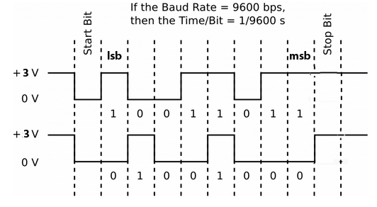
\[y = \frac{(x - x_{min}) \cdot (y_{max} - y_{min})}{(x_{max} - x_{min})} + y_{min}\]The UART serial bits are shown below. It takes 10 bit-times to send 8 bits.
Some important code pieces
Note that these codes won’t work as they are. The purpose of these code snippets is to gather common ones and their configurations in one place.
Main function
#include "main.h"
/* USER CODE BEGIN 0 */
/* You can add extra code here such as for global variables, function definitions etc. */

int main(void)
{
  /* USER CODE BEGIN 1 */
  /* You can add extra code here such as for local variables, function calls etc. */
  HAL_Init();
  SystemClock_Config();

  MX_GPIO_Init();
  MX_USART3_UART_Init();
  MX_TIM1_Init();
  MX_ADC1_Init();
  MX_DAC_Init();

  /* USER CODE BEGIN 2 */
  /* You can add extra code here such as for initializing variables, starting timers etc. */
  HAL_TIM_PWM_Start(&htim1, TIM_CHANNEL_4);
  __HAL_TIM_SET_COMPARE(&htim1, TIM_CHANNEL_4, SERVO_PULSE_MIN);

  HAL_DAC_Start(&hdac, DAC_CHANNEL_1);

  volatile uint32_t timer_val;
  HAL_TIM_Base_Start(&htim2);
  timer_val = __HAL_TIM_GET_COUNTER(&htim2);

  while (1)
  {

    /* USER CODE BEGIN 3 */
    /* You can add extra code for things you want to run in the loop. */
    // sprintf
    char transmit_buffer[100];
	  uint8_t timeout = 100;
	  int tall = 50;
    sprintf(transmit_buffer, "Sensorvalue : %d \n", tall);
    HAL_UART_Transmit(&huart3, transmit_buffer, strlen(transmit_buffer), timeout);
    HAL_Delay(1000);
    tall++;

    // DC motor control
    // Set Direction CW (IN_1A HIGH, IN_2A LOW)
    HAL_GPIO_WritePin(IN_1A_GPIO_Port, IN_1A_Pin, GPIO_PIN_SET);
    HAL_GPIO_WritePin(IN_2A_GPIO_Port, IN_2A_Pin, GPIO_PIN_RESET);
    // Apply current speed
    __HAL_TIM_SET_COMPARE(&htim1, TIM_CHANNEL_1, current_pwm);
    break;

    // Servo motor control
    for(current_pulse = SERVO_PULSE_MIN; current_pulse <= SERVO_PULSE_MAX; current_pulse++) {
        __HAL_TIM_SET_COMPARE(&htim1, TIM_CHANNEL_4, current_pulse);
        HAL_Delay(SWEEP_DELAY); // Slow down the sweep for visibility
    }

    // Button-LED control
    if(HAL_GPIO_ReadPin(Button_Pin_GPIO_Port, Button_Pin_Pin)){
      HAL_GPIO_WritePin(LED_Pin_GPIO_Port, LED_Pin_Pin, GPIO_PIN_SET);
    }
    else{
      HAL_GPIO_WritePin(LED_Pin_GPIO_Port, LED_Pin_Pin, GPIO_PIN_RESET);
    }

    // Potentiometer - LED control
    HAL_ADC_Start(&hadc1);
    HAL_ADC_PollForConversion(&hadc1, HAL_MAX_DELAY);
    adc_value = HAL_ADC_GetValue(&hadc1);
    HAL_ADC_Stop(&hadc1);
    pwm_pulse = (uint32_t)adc_value * PWM_PERIOD_VALUE / ADC_MAX_VALUE;
    __HAL_TIM_SET_COMPARE(&htim1, TIM_CHANNEL_1, pwm_pulse);
    HAL_Delay(10);

    // DAC
    for(dac_value = 0; dac_value <= 4095; dac_value++) {
        HAL_DAC_SetValue(&hdac, DAC_CHANNEL_1, DAC_ALIGN_12B_R, dac_value);
        HAL_Delay(1); // Small delay to observe the change
    }

    // Timer 1 counter
    if (__HAL_TIM_GET_COUNTER(&htim1) - timer_val >= 100000)
    {
      HAL_GPIO_TogglePin(LD1_GPIO_Port, LD1_Pin);
      timer_val = __HAL_TIM_GET_COUNTER(&htim1);
    }

    // I2C
    // 1. Read 6 bytes of acceleration data (X MSB, X LSB, Y MSB, Y LSB, Z MSB, Z LSB)
    HAL_I2C_Mem_Read(&hi2c1, MMA8451_ADDRESS, MMA8451_OUT_X_MSB, 1, RxData, 6, HAL_MAX_DELAY);

    // 2. Process the 14-bit data. The data is Left-Justified.
    Accel_X = (int16_t)((RxData[0] << 8) | RxData[1]) >> 2;
    Accel_Y = (int16_t)((RxData[2] << 8) | RxData[3]) >> 2;
    Accel_Z = (int16_t)((RxData[4] << 8) | RxData[5]) >> 2;

    // 3. Conversion to g-force values (2g range / 8192 counts)
    #define ACCEL_RANGE_G 2.0f
    #define ACCEL_MAX_RAW 8192.0f

    float Accel_X_g, Accel_Y_g, Accel_Z_g;

    Accel_X_g = ((float)Accel_X / ACCEL_MAX_RAW) * ACCEL_RANGE_G;
    Accel_Y_g = ((float)Accel_Y / ACCEL_MAX_RAW) * ACCEL_RANGE_G;
    Accel_Z_g = ((float)Accel_Z / ACCEL_MAX_RAW) * ACCEL_RANGE_G;
  }
}

/* USER CODE BEGIN 4 */
/* You can add extra code here such as for defining interrupt calls, custom functions etc. */
void SystemClock_Config(void)
{
  RCC_OscInitTypeDef RCC_OscInitStruct = {0};
  RCC_ClkInitTypeDef RCC_ClkInitStruct = {0};

  /** Configure the main internal regulator output voltage
  */
  __HAL_RCC_PWR_CLK_ENABLE();
  __HAL_PWR_VOLTAGESCALING_CONFIG(PWR_REGULATOR_VOLTAGE_SCALE3);

  /** Initializes the RCC Oscillators according to the specified parameters
  * in the RCC_OscInitTypeDef structure.
  */
  RCC_OscInitStruct.OscillatorType = RCC_OSCILLATORTYPE_HSI;
  RCC_OscInitStruct.HSIState = RCC_HSI_ON;
  RCC_OscInitStruct.HSICalibrationValue = RCC_HSICALIBRATION_DEFAULT;
  RCC_OscInitStruct.PLL.PLLState = RCC_PLL_ON;
  RCC_OscInitStruct.PLL.PLLSource = RCC_PLLSOURCE_HSI;
  RCC_OscInitStruct.PLL.PLLM = 8;
  RCC_OscInitStruct.PLL.PLLN = 108;
  RCC_OscInitStruct.PLL.PLLP = RCC_PLLP_DIV2;
  RCC_OscInitStruct.PLL.PLLQ = 2;
  RCC_OscInitStruct.PLL.PLLR = 2;
  if (HAL_RCC_OscConfig(&RCC_OscInitStruct) != HAL_OK)
  {
    Error_Handler();
  }

  /** Activate the Over-Drive mode
  */
  if (HAL_PWREx_EnableOverDrive() != HAL_OK)
  {
    Error_Handler();
  }

  /** Initializes the CPU, AHB and APB buses clocks
  */
  RCC_ClkInitStruct.ClockType = RCC_CLOCKTYPE_HCLK|RCC_CLOCKTYPE_SYSCLK
                              |RCC_CLOCKTYPE_PCLK1|RCC_CLOCKTYPE_PCLK2;
  RCC_ClkInitStruct.SYSCLKSource = RCC_SYSCLKSOURCE_PLLCLK;
  RCC_ClkInitStruct.AHBCLKDivider = RCC_SYSCLK_DIV1;
  RCC_ClkInitStruct.APB1CLKDivider = RCC_HCLK_DIV2;
  RCC_ClkInitStruct.APB2CLKDivider = RCC_HCLK_DIV1;

  if (HAL_RCC_ClockConfig(&RCC_ClkInitStruct, FLASH_LATENCY_3) != HAL_OK)
  {
    Error_Handler();
  }
}
Initializer functions
MX_GPIO_Init()
static void MX_GPIO_Init(void)
{
  GPIO_InitTypeDef GPIO_InitStruct = {0};

  /* GPIO Ports Clock Enable */
  __HAL_RCC_GPIOC_CLK_ENABLE();
  __HAL_RCC_GPIOH_CLK_ENABLE();
  __HAL_RCC_GPIOA_CLK_ENABLE();
  __HAL_RCC_GPIOB_CLK_ENABLE();
  __HAL_RCC_GPIOD_CLK_ENABLE();
  __HAL_RCC_GPIOG_CLK_ENABLE();

  /*Configure GPIO pin Output Level */
  HAL_GPIO_WritePin(GPIOB, LD1_Pin|LD3_Pin|LD2_Pin, GPIO_PIN_RESET);

  /*Configure GPIO pin Output Level */
  HAL_GPIO_WritePin(USB_PowerSwitchOn_GPIO_Port, USB_PowerSwitchOn_Pin, GPIO_PIN_RESET);

  /*Configure GPIO pin : USER_Btn_Pin */
  GPIO_InitStruct.Pin = USER_Btn_Pin;
  GPIO_InitStruct.Mode = GPIO_MODE_IT_RISING;
  GPIO_InitStruct.Pull = GPIO_NOPULL;
  HAL_GPIO_Init(USER_Btn_GPIO_Port, &GPIO_InitStruct);

  /*Configure GPIO pins : LD1_Pin LD3_Pin LD2_Pin */
  GPIO_InitStruct.Pin = LD1_Pin|LD3_Pin|LD2_Pin;
  GPIO_InitStruct.Mode = GPIO_MODE_OUTPUT_PP;
  GPIO_InitStruct.Pull = GPIO_NOPULL;
  GPIO_InitStruct.Speed = GPIO_SPEED_FREQ_LOW;
  HAL_GPIO_Init(GPIOB, &GPIO_InitStruct);

  /*Configure GPIO pin : USB_PowerSwitchOn_Pin */
  GPIO_InitStruct.Pin = USB_PowerSwitchOn_Pin;
  GPIO_InitStruct.Mode = GPIO_MODE_OUTPUT_PP;
  GPIO_InitStruct.Pull = GPIO_NOPULL;
  GPIO_InitStruct.Speed = GPIO_SPEED_FREQ_LOW;
  HAL_GPIO_Init(USB_PowerSwitchOn_GPIO_Port, &GPIO_InitStruct);

  /*Configure GPIO pin : USB_OverCurrent_Pin */
  GPIO_InitStruct.Pin = USB_OverCurrent_Pin;
  GPIO_InitStruct.Mode = GPIO_MODE_INPUT;
  GPIO_InitStruct.Pull = GPIO_NOPULL;
  HAL_GPIO_Init(USB_OverCurrent_GPIO_Port, &GPIO_InitStruct);
}
MX_USARTX_UART_Init()
static void MX_USART3_UART_Init(void)
{
  huart3.Instance = USART3;
  huart3.Init.BaudRate = 115200;
  huart3.Init.WordLength = UART_WORDLENGTH_8B;
  huart3.Init.StopBits = UART_STOPBITS_1;
  huart3.Init.Parity = UART_PARITY_NONE;
  huart3.Init.Mode = UART_MODE_TX_RX;
  huart3.Init.HwFlowCtl = UART_HWCONTROL_NONE;
  huart3.Init.OverSampling = UART_OVERSAMPLING_16;
  huart3.Init.OneBitSampling = UART_ONE_BIT_SAMPLE_DISABLE;
  huart3.AdvancedInit.AdvFeatureInit = UART_ADVFEATURE_NO_INIT;
  if (HAL_UART_Init(&huart3) != HAL_OK)
  {
    Error_Handler();
  }
}
MX_DAC_Init()
static void MX_DAC_Init(void)
{
  DAC_ChannelConfTypeDef sConfig = {0};

  /** DAC Initialization
  */
  hdac.Instance = DAC;
  if (HAL_DAC_Init(&hdac) != HAL_OK)
  {
    Error_Handler();
  }

  /** DAC channel OUT1 config
  */
  sConfig.DAC_Trigger = DAC_TRIGGER_NONE;
  sConfig.DAC_OutputBuffer = DAC_OUTPUTBUFFER_ENABLE;
  if (HAL_DAC_ConfigChannel(&hdac, &sConfig, DAC_CHANNEL_1) != HAL_OK)
  {
    Error_Handler();
  }
}
MX_TIMX_Init()
static void MX_TIM1_Init(void)
{
  TIM_ClockConfigTypeDef sClockSourceConfig = {0};
  TIM_MasterConfigTypeDef sMasterConfig = {0};
  TIM_OC_InitTypeDef sConfigOC = {0};
  TIM_BreakDeadTimeConfigTypeDef sBreakDeadTimeConfig = {0};

  htim1.Instance = TIM1;
  htim1.Init.Prescaler = 108-1;
  htim1.Init.CounterMode = TIM_COUNTERMODE_UP;
  htim1.Init.Period = 999;
  htim1.Init.ClockDivision = TIM_CLOCKDIVISION_DIV1;
  htim1.Init.RepetitionCounter = 0;
  htim1.Init.AutoReloadPreload = TIM_AUTORELOAD_PRELOAD_DISABLE;
  if (HAL_TIM_Base_Init(&htim1) != HAL_OK)
  {
    Error_Handler();
  }
  sClockSourceConfig.ClockSource = TIM_CLOCKSOURCE_INTERNAL;
  if (HAL_TIM_ConfigClockSource(&htim1, &sClockSourceConfig) != HAL_OK)
  {
    Error_Handler();
  }
  if (HAL_TIM_PWM_Init(&htim1) != HAL_OK)
  {
    Error_Handler();
  }
  HAL_TIM_MspPostInit(&htim1);
}
Timer and external callbacks
void HAL_TIM_TriggerCallback(TIM_HandleTypeDef *htim){
  if (htim->Instance == TIM3) // Interrupt on TIM3
    {
      HAL_GPIO_TogglePin(LD1_GPIO_Port, LD1_Pin); // Toggle LED on ANY edge detected
    }
}

// Callback-function for interrupt
void HAL_GPIO_EXTI_Callback(uint16_t GPIO_Pin)
{
    if (GPIO_Pin == GPIO_PIN_13) // Check if PB13 is the one pressed
    {
        led_state ^= 1; // Toggle the LED state
        if (led_state)
        {
            HAL_GPIO_WritePin(GPIOA, GPIO_PIN_15, GPIO_PIN_SET); // Turn on LED
        }
        else
        {
            HAL_GPIO_WritePin(GPIOA, GPIO_PIN_15, GPIO_PIN_RESET); // Turn off LED
        }
    }
}
MX_ADCX_Init()
static void MX_ADC1_Init(void)
{
  ADC_ChannelConfTypeDef sConfig = {0};
  /** Configure the global features of the ADC (Clock, Resolution, Data Alignment and number of conversion)
  */
  hadc1.Instance = ADC1;
  hadc1.Init.ClockPrescaler = ADC_CLOCK_SYNC_PCLK_DIV4;
  hadc1.Init.Resolution = ADC_RESOLUTION_12B;
  hadc1.Init.ScanConvMode = ADC_SCAN_DISABLE;
  hadc1.Init.ContinuousConvMode = DISABLE;
  hadc1.Init.DiscontinuousConvMode = DISABLE;
  hadc1.Init.ExternalTrigConvEdge = ADC_EXTERNALTRIGCONVEDGE_NONE;
  hadc1.Init.ExternalTrigConv = ADC_SOFTWARE_START;
  hadc1.Init.DataAlign = ADC_DATAALIGN_RIGHT;
  hadc1.Init.NbrOfConversion = 1;
  hadc1.Init.DMAContinuousRequests = DISABLE;
  hadc1.Init.EOCSelection = ADC_EOC_SINGLE_CONV;
  if (HAL_ADC_Init(&hadc1) != HAL_OK)
  {
    Error_Handler();
  }

  /** Configure for the selected ADC regular channel its corresponding rank in the sequencer and its sample time.
  */
  sConfig.Channel = ADC_CHANNEL_3;
  sConfig.Rank = ADC_REGULAR_RANK_1;
  sConfig.SamplingTime = ADC_SAMPLETIME_3CYCLES;
  if (HAL_ADC_ConfigChannel(&hadc1, &sConfig) != HAL_OK)
  {
    Error_Handler();
  }
}