Lecture 3 - Timers and Interrupt 1
Clock
Undeniably the most important thing in a digital system. Therefore, it is fundamental to understand the concept of clock, to understand how an embedded system works. A clock is the heartbeat of your controller. Imagine your microcontroller as a tiny orchestra. For every instrument (or peripheral) to play in perfect harmony, they need a conductor keeping the beat. That conductor is the clock.
The clock is essentially an oscillating signal that synchronizes all operations within the microcontroller. Every instruction, every data transfer, every peripheral action happens in sync with this clock signal. The faster the clock, generally, the faster your microcontroller can execute instructions.
Nice to watch: Why clock is everything?
On the STM32F767, we have a sophisticated clock system. It’s not just one clock; there’s a whole hierarchy:
- HSE (High-Speed External): This is typically an external crystal oscillator. It’s very accurate and stable, making it a good choice for the main system clock.
- HSI (High-Speed Internal): An internal RC oscillator. It’s less accurate than an external crystal but is ready to use immediately upon power-up, making it useful for initial startup or applications where high precision isn’t critical.
- LSE (Low-Speed External): Another external crystal, usually for real-time clock (RTC) applications due to its low frequency and power consumption.
- LSI (Low-Speed Internal): An internal RC oscillator, primarily used for the independent watchdog and the RTC in low-power modes.
- PLL (Phase-Locked Loop): This is a frequency multiplier. We often use the PLL to take a relatively low-frequency source (like HSE or HSI) and multiply it up to a much higher frequency to drive the main system clock (SYSCLK) and various peripherals.
In STM32 microcontrollers, SYSCLK (System Clock) is the main clock source for the entire system, while HCLK (AHB Clock) is a derived clock used by the CPU and AHB bus. SYSCLK can be generated from various sources like HSI, HSE, or PLL, and then HCLK is derived from SYSCLK by a configurable prescaler. This means that HCLK runs at a lower frequency than SYSCLK, and it is used to clock the core and other AHB peripherals.
SYSCLK (System Clock): It is the main clock for the STM32 microcontroller. It’s source can be selected from:
- Internal high-speed oscillator (HSI)
- External high-speed oscillator (HSE)
- PLL (Phase-Locked Loop)
Usually the highest frequency at which the microcontroller operates.
HCLK (AHB Clock): It is a clock derived from SYSCLK. Clocks the CPU core, the AHB bus, and some AHB peripherals. Its frequency is typically lower than SYSCLK, as it is divided down using a prescaler. This helps:
- Optimize power consumption
-
Allow different peripherals to run at different speeds If SYSCLK = 100 MHz and the prescaler is set to divide by 2, then HCLK = 50 MHz.
- APB1 (Advanced Peripheral Bus 1): This bus typically runs at a lower frequency than HCLK, set by a prescaler. It connects to peripherals like timers (TIM2–TIM7, TIM12–TIM14), USART2/3, I2C1/2/3, SPI2/3, and others. The lower frequency helps reduce power consumption for slower peripherals.
- APB2 (Advanced Peripheral Bus 2): This bus can run at the same frequency as HCLK or at a divided rate, depending on the prescaler setting. It connects to higher-speed peripherals such as TIM1, TIM8, USART1/6, SPI1, and the ADCs.
The prescaler values for APB1 and APB2 are set in the RCC (Reset and Clock Control) registers. For example, if HCLK is 100 MHz and the APB1 prescaler is set to 4, then the APB1 clock will be 25 MHz. This means that all peripherals on APB1 will operate at 25 MHz.
Timer
While the clock provides the constant beat, timers are like sophisticated stopwatches or alarm clocks within your microcontroller. They are specialized peripherals designed to:
- Measure time intervals (e.g., how long did that button press last?)
- Generate delays (e.g., wait for 500 milliseconds before turning on an LED)
- Trigger events at regular intervals (e.g., blink an LED every second)
- Generate PWM (Pulse Width Modulation) signals (e.g., control the brightness of an LED or the speed of a motor)
- Count external events (e.g., how many times was that sensor tripped?)
The STM32F767 is equipped with a rich set of timers:
- General-purpose timers (TIMx): very versatile, used for most timing applications
- Advanced-control timers (TIMx): offer more advanced features, particularly useful for motor control and power conversion
- Basic timers (TIMx): simpler timers, often used for basic time-base generation
- SysTick timer: a 24-bit down-counter built into the ARM Cortex-M core, often used for operating system ticks or simple delays
Why does this matter?
- Some peripherals (especially timers) have their own internal logic to compensate for the prescaler. For example, if a timer is on APB1 and the prescaler is not 1, the timer’s input clock is automatically doubled to maintain correct timing. This is important when configuring timer frequencies and baud rates for communication peripherals.
- When you configure peripherals in STM32CubeMX or in your code, you must be aware of which bus they are attached to and what their actual clock frequency is. This ensures that your timing calculations (for delays, baud rates, PWM, etc.) are accurate.
Summary Table:
| Bus | Typical Peripherals | Derived From | Prescaler | Example Frequency |
|---|---|---|---|---|
| AHB | CPU, DMA, RAM, Flash | SYSCLK | Yes | 216 MHz |
| APB1 | TIM2–TIM7, USART2/3, I2C1/2 | HCLK | Yes | 54 MHz |
| APB2 | TIM1/8, USART1/6, ADCs | HCLK | Yes | 108 MHz |
Always check the reference manual and your clock configuration to know exactly how fast each peripheral is running!
Which timer to use?
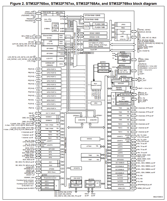
Let’s look at the block diagram of our microcontroller in the datasheet. In Figure 2 on page 20, you can see how the pins are connected:
Section 3.23 explains which timers are available in our microcontroller. Let’s have a look at Table 6.
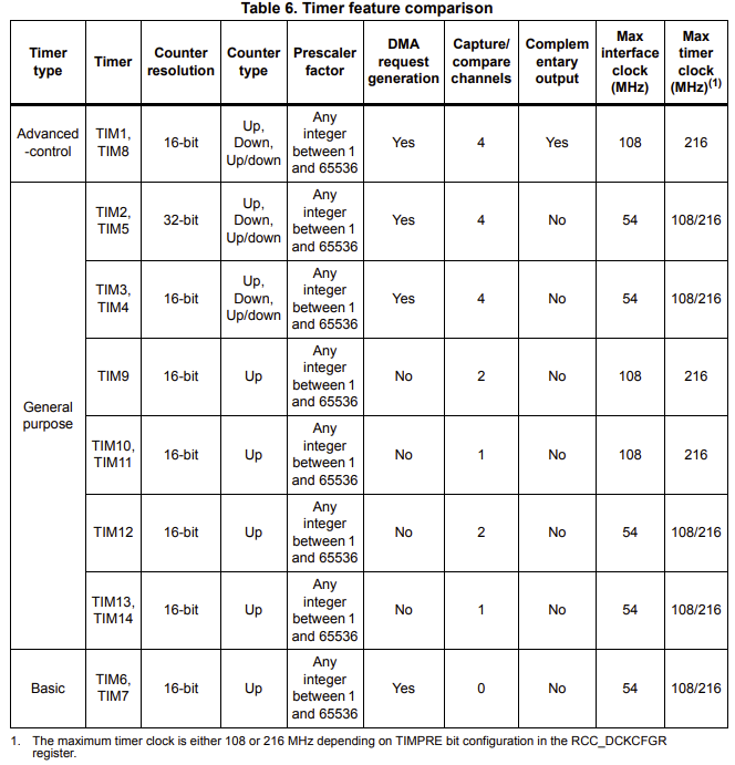
Overall Structure: There are three main timer types:
- Advanced-control: These are the most feature-rich timers, typically used for complex applications like motor control, power conversion, and high-resolution PWM.
- General purpose: These are versatile timers suitable for a wide range of applications, including general-purpose timing, PWM generation, input capture, output compare, and more.
- Basic: These are simpler timers, primarily used for basic timing and delay generation.
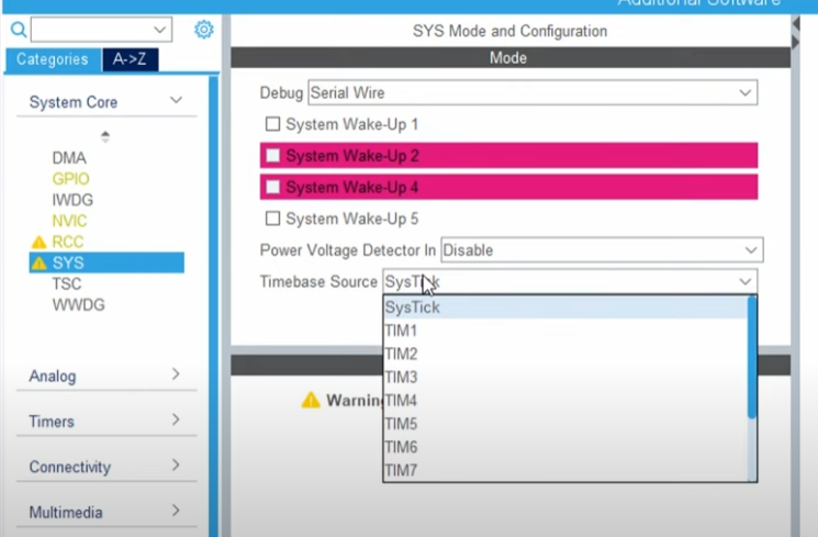
SysTick timer
The SysTick timer on the STM32F767 microcontroller is a 24-bit down-counting timer embedded within the Cortex-M7 core itself, making it a highly integrated and essential component for real-time operating systems (RTOS) and general-purpose timing. It offers a simple yet effective mechanism for generating periodic interrupts, typically configured to fire at a regular interval (e.g., every millisecond) to drive the OS tick. Its preloader value is derived directly from the system clock (HCLK), ensuring precise and synchronized timing.
DO NOT MESS WITH SYSTICK TIMER! It sources the main delay. In some cases one might want to use it, especially real-time operations, but then, don’t forget to assign your timebase source, as well.
Watchdog timer
A watchdog timer (WDT) is a crucial hardware or software component designed to enhance the reliability and robustness of embedded systems. It acts like a “watchdog” (hence the name) that constantly monitors the microcontroller’s (or your PC’s in this matther) operation to detect and recover from malfunctions, such as software crashes, infinite loops, or system hangs.
Imagine you have a computer or a device that needs to run continuously, like a medical device, a factory robot, or even your car’s engine control unit. What if the software inside it gets “stuck” or freezes, maybe due to a tiny glitch or a bug? If it just stops, it could cause big problems or even be dangerous. That’s where a watchdog timer comes in! Think of it like a loyal guard dog for your computer. This “dog” is always watching to make sure the computer is doing its job.
The STM32F767 microcontroller incorporates two types of watchdog timers to enhance system reliability and prevent software malfunctions: the Independent Watchdog (IWDG) and the Window Watchdog (WWDG). Both are designed to reset the microcontroller if the application code enters an undesirable state, such as an infinite loop or a deadlock. The IWDG operates from its own independent low-speed internal RC oscillator (LSI), making it robust against failures of the main system clock. It’s a simple down-counter that triggers a reset if not “fed” (reloaded) within a defined timeout period. In contrast, the WWDG offers more sophisticated control, requiring the application to refresh it only within a specific “window” of time. If the WWDG is refreshed too early or too late, it will trigger a system reset, allowing detection of both abnormally slow and abnormally fast execution, which can be crucial for safety-critical applications. If you are curious about the details, controllerstech.com has a nice tutorial. However, the details of the SysTick and Watchdog timer are outside the scope of this course.
Exercise: LED blink with correct clock settings
In the previous exercises, we haven’t done anything with the clock settings. Our code worked just fine but it is time to stop “default settings”. As you remember the blink rate is a bit slower than 500ms, right? It is because we haven’t configured the clock settings properly and we have lots of pins configured by default even if we don’t use. We will fix the blink rate issue NOW!.
- Open a new STM32CubeMX project.
- Select STM32F767 board, start project, but DO NOT SELECT default mode.
- You should see some pins are orange. We want these to be gone, as well:
Pinout (at the top) > Clear pinouts - Set PB0 as GPIO_Output.
- On the left
System Core > RCC > HSE: Crystal/Ceramic Resonator(RCC: Reset and Clock Control) - Master Clock Output: Checked. (only for a possible debugging)
- On the left
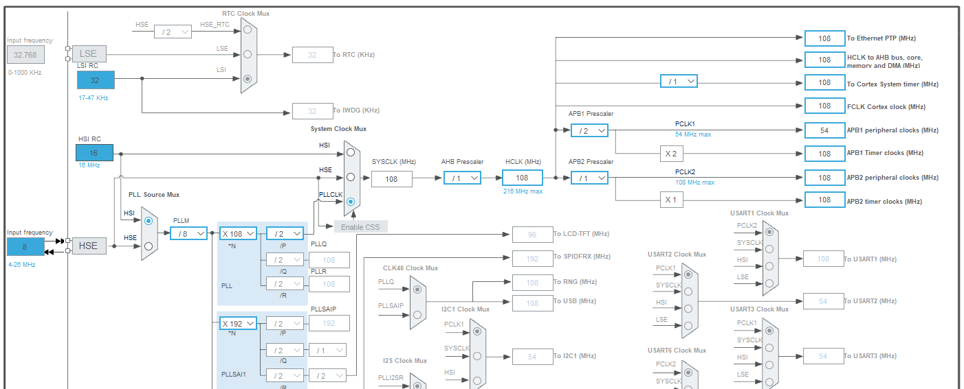
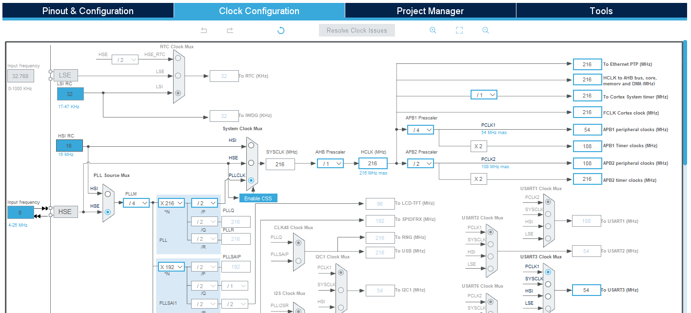
System Core > GPIO > Configuration > PB0 >Change user label toLD1 - Go to Clock Configuration. Set these values:
- Go to Project Manager a. Give descriptive name to your project b. Application structure: Basic c. Toolchain/IDE: STM32CubeIDE (Uncheck “Generate under root” box)
- Generate project.
- Copy platformio.ini file from your prior projects.
- Open the project in PlatformIO.
- Add this code after
/*USER CODE BEGIN 3*/in main.c:HAL_GPIO_TogglePin(LD1_GPIO_Port, LD1_Pin); HAL_Delay(500); - Build and Upload
Notice: IDK why the default clock configuration doesn’t work properly. Let me know if you find out the error.
Interrupts
In the previous LED blink example, we have done nothing between toggles. We put a simple delay with HAL_Delay(500);, which literally halted the system for an entire 500 milliseconds! Do you realize how wasteful it is? Well, in such a simple project, it is not an issue. We have some 500 ms to spend, however, it might not be the case. Therefore, we need to figure our can we do this timed tasks more efficiently.
Similarly, in the button-LED example, we checked the button state in every loop. It is called “polling”. However, we did it so many unnecessary times. Couldn’t it be better if our button gives us a heads up if something changes on its side.
Welcome to the world of INTERRUPTS! A interrupt is some form of external signal that interrupts the main process. When an interrupt occurs the current execution state of the main process is stored, before a different process (the ISR, or interrupt service routine) takes over. When the interrupt service routine has completed, execution control is returned to the main process.
Interrupts are useful for making the system responsive to external events while avoiding constant polling of the possible external event sources. Sometimes the ISR may simply set a flag, or publish a message in a event queue such that the main process can take appropriate action when it is ready to do so.
Polling:

Interrupt:

An interrupt is a signal that tells the processor to immediately stop what it is doing and handle some high priority processing. That high priority processing is called an Interrupt Handler. An interrupt handler is like any other void function. If you write one and attach it to an interrupt, it will get called whenever that interrupt signal is triggered. When you return from the interrupt handler, the processor goes back to continue what it was doing before.
Interrupts can be generated from several sources:
- Timer interrupts from one of the microcontrollers timers.
- External Interrupts from a change in state of one of the external interrupt pins.
- Pin-change interrupts from a change in state of any one of a group of pins.
Exercise: LED blink with timers
In this exercise we willt toggle the LED when the time is right. rather than waiting for the rignt time to come
For this example, we will use TIM2, which is a general-purpose timer. It can count upto 32-bits, both upwards and downwards. It does not intervene with any other features that we need in this project.
- Open a new STM32CubeMX project.
- Select STM32F767 board, start project, but DO NOT SELECT default mode.
- You should see some pins are orange. We want these to be gone, as well:
Pinout (at the top) > Clear pinouts - Set PB0 as GPIO_Output.
- On the left
System Core > RCC > HSE: Crystal/Ceramic Resonator(RCC: Reset and Clock Control) - Master Clock Output: Checked. (only for a possible debugging)
- Find PB0 on the chip, and set it to GPIO_Output. And then, right click on the pin > edit user label
- Make sure the settings look like this so far on the left
System Core > GPIO > Configuration > PB0 >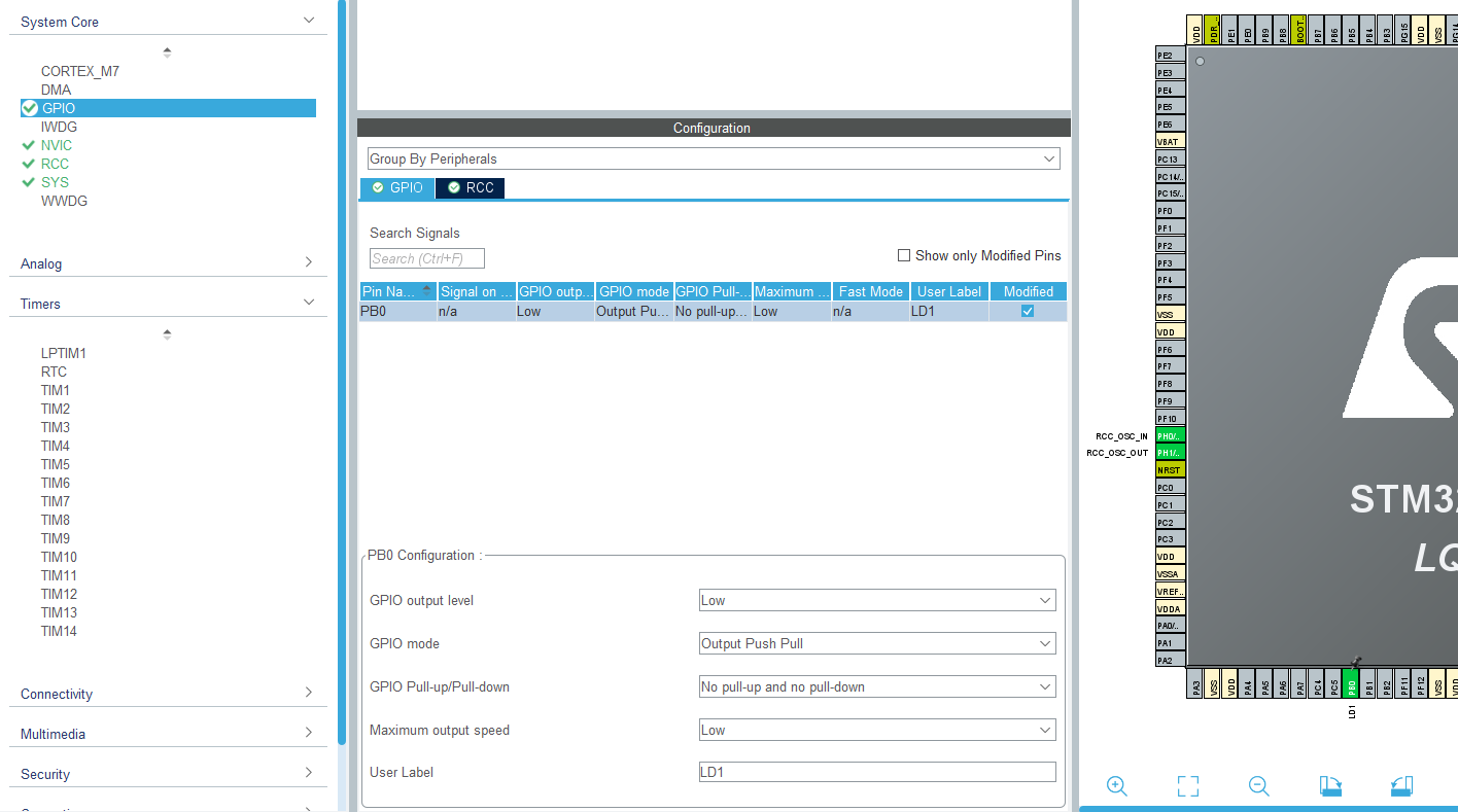
- Make sure the settings look like this so far on the left
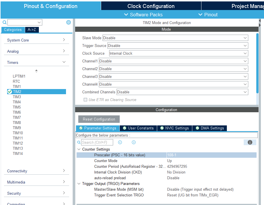
- On the left
Timers > TIM2 > Clock source -> Internal clockand in Parameter settingsPrescalar -> 108-1 - Go to Clock Configuration. Set these values:
- Go to Project Manager a. Give descriptive name to your project b. Application structure: Basic c. Toolchain/IDE: STM32CubeIDE (Uncheck “Generate under root” box)
- Generate project.
- Create a platformio.ini file and copy this:
[env:nucleo_f767zi] platform = ststm32 board = nucleo_f767zi framework = stm32cube build_flags = -IInc upload_protocol = stlink debug_tool = stlink debug_build_flags = -O0 -g -ggdb - Open the project in PlatformIO.
- Add this code after
/* USER CODE BEGIN 1 */in main.c:// volatile keyword is very important! // it is not the MCU but a timer responsible in changing this variable // So your compiler optimizes this variable out // thinking that it is unused. Yeah, pretty stupid. volatile uint32_t timer_val; - Add this code after
/* USER CODE BEGIN 2 */in main.c:// Start timer HAL_TIM_Base_Start(&htim2); // Get current time (microseconds) timer_val = __HAL_TIM_GET_COUNTER(&htim2); - Add this code after
/* USER CODE BEGIN 3 */in main.c:if (__HAL_TIM_GET_COUNTER(&htim2) - timer_val >= 1000000) { HAL_GPIO_TogglePin(LD1_GPIO_Port, LD1_Pin); timer_val = __HAL_TIM_GET_COUNTER(&htim2); } - Build and Upload
Explanation
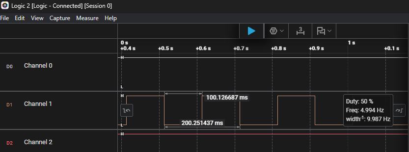
- Total Blink Period: 500ms (ON) + 500ms (OFF) = 1000ms = 1 second.
- Blink Frequency: 1 Hz.
- Our
SystemClock_Configsets theSYSCLKto 108 MHz. It makes makes theAPB1bus clock for peripherals \(54 MHz\) and for timers \(108 MHz\), including forTIM2. - When we set the prescalar fot
TIM2as $108-1$, we actually set the counter forTIM2to tick every 1us. - Therefore
if (__HAL_TIM_GET_COUNTER(&htim2) - timer_val >= 1000000)means “blink every second”!
Timer calculations
As you realized, we wrote down some numbers like 108 Hz for HCLK, 108-1 for prescalar, (__HAL_TIM_GET_COUNTER(&htim2) - timer_val >= 100000) in our code, but how can we decide what to write? How can we calculate them? Let’s break down the essential components for accurate timer configurations.
Timer Frequency Calculation
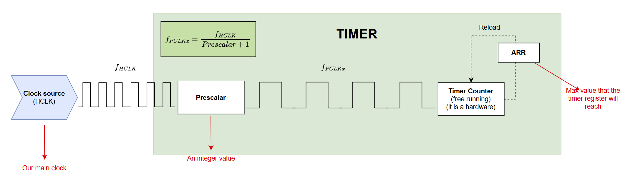
Note that HCLK is our main clock. It means that this clock will ignite other busses like APB (Advanced Perpheral Bus) to set PCLKs (Peripheral Clocks). Look at the clock configuration on CubeMX. By setting it to 108 MHz, our main clock generates \(108\times 10^6\) ticks every second!
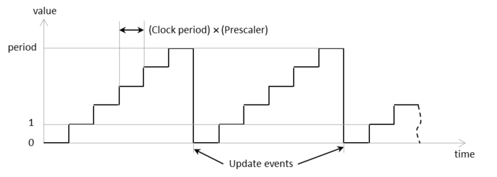
Each timer has an internal counter that increments based on a clock source. The rate at which this counter increments is the “timer tick frequency.” The timer’s input clock is first divided by the Prescaler and then used to increment the counter.
The relationship between HCLK and PCLK is like this: \(PCLKx = \dfrac{HCLK}{(APBx\_Prescaler + 1)}\)
which means that if you set your HCLK = 108 Mhz, and AHBx Prescalar to /2, then your peripheral clock will work at half speed of your main clock, but with x2 multiplier before the APB1 timer clocks, your timers connected to APB1 with have 108MHz internal clock.
Note that in PWM lecture, you will have Auto-reload register for PWM frequency, but we are not dealing with that yet.
Prescalar
A Prescaler Value (PSC) is a 16-bit or 32-bit register value. The timer’s input clock is divided by (PSC+1) before it increments the counter.
- Example: If PSC = 107, the division factor is (107+1)=108.
Each timer has its own prescalar. This is what we adjusted in timer configurations. We sat it 108-1. We could have set it 107 directly but writing like is a bit more obvious how we come up there.
Based on the datasheet TIM2 is connected to ABP1:
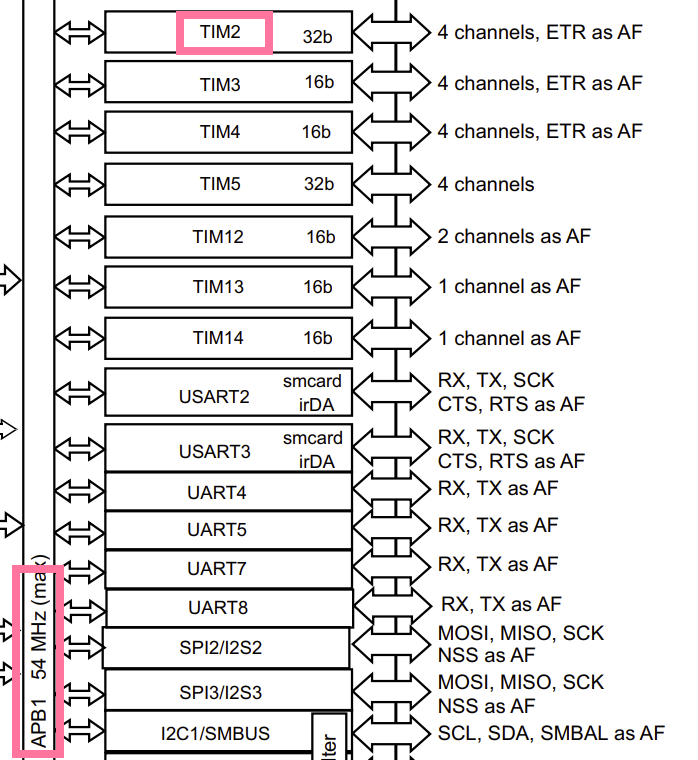
We can see that we sat APB1 Timer clocks to 108 Mhz.
With Prescaler = 108 - 1 = 107, the timer clock frequency will be:
\(108,000,000 Hz / (107 + 1) = 108,000,000 Hz / 108 = 1,000,000 Hz\).
This means each tick of the counter is \(1 / 1,000,000 Hz = 1 us\).
Our condition if (__HAL_TIM_GET_COUNTER(&htim2) - timer_val >= 100000) checks for 100,000 timer ticks.
Therefore, the delay will be 100000 ticks * 1 us/tick = 100000 us = 100 milliseconds. The LED will toggle every 100ms, so a full blink cycle (on and off) will be 200ms. We can see that by checking the positive side of LD1 on our logic analyzer.
You can also use this online timer calculator for STM32.
Timer overload
So, we know that our timer counter has a limited capacity. The counter value is stored in a 32-bits register. It is obvious (at least I hope) that after the register 0xFF, it will restart counting from 0x00 again. The highest bit (33th bit) will overflow and we will lose it forever.
Then the question: what is the maximum time that we can measure with this timer?
\[2^{32} - 1 = 4,294,967,295\]and each tick was calculated 1 us, so converting to Larger Units (for better understanding):
- Milliseconds (ms): 4,294,967,295 µs ÷ 1,000 µs/ms = 4,294,967.295 ms
- Seconds (s): 4,294,967.295 ms ÷ 1,000 ms/s = 4,294.967295 s
- Minutes (min): 4,294.967295 s ÷ 60 s/min ≈ 71.58 minutes
- Hours (h): 71.58 min ÷ 60 min/h ≈ 1.19 hours
Therefore, we need to choose a different prescalar if we want to measure longer time.
Note:
- What is the maximum minutes that you can count with TIM3 with prescalar 27-1?
- What prescalar you should choose to be able to count with TIM3 for more than one-day?
- Can you count more than 1-week with TIM3? If so, which prescalar? If not, what would you do to change to be able to count upto a week?
Timer modes
As you might have realized, timers have various purposes, and therefore, they are used extensively! By setting the timer into correct mode, the majority of your task will be done. Here you will find what those modes are and when to use them.
STM32 Timer Modes - Functional Modes (what the timer does)
We can group STM32 timer modes into core modes (time base), output modes, input modes, and special modes:
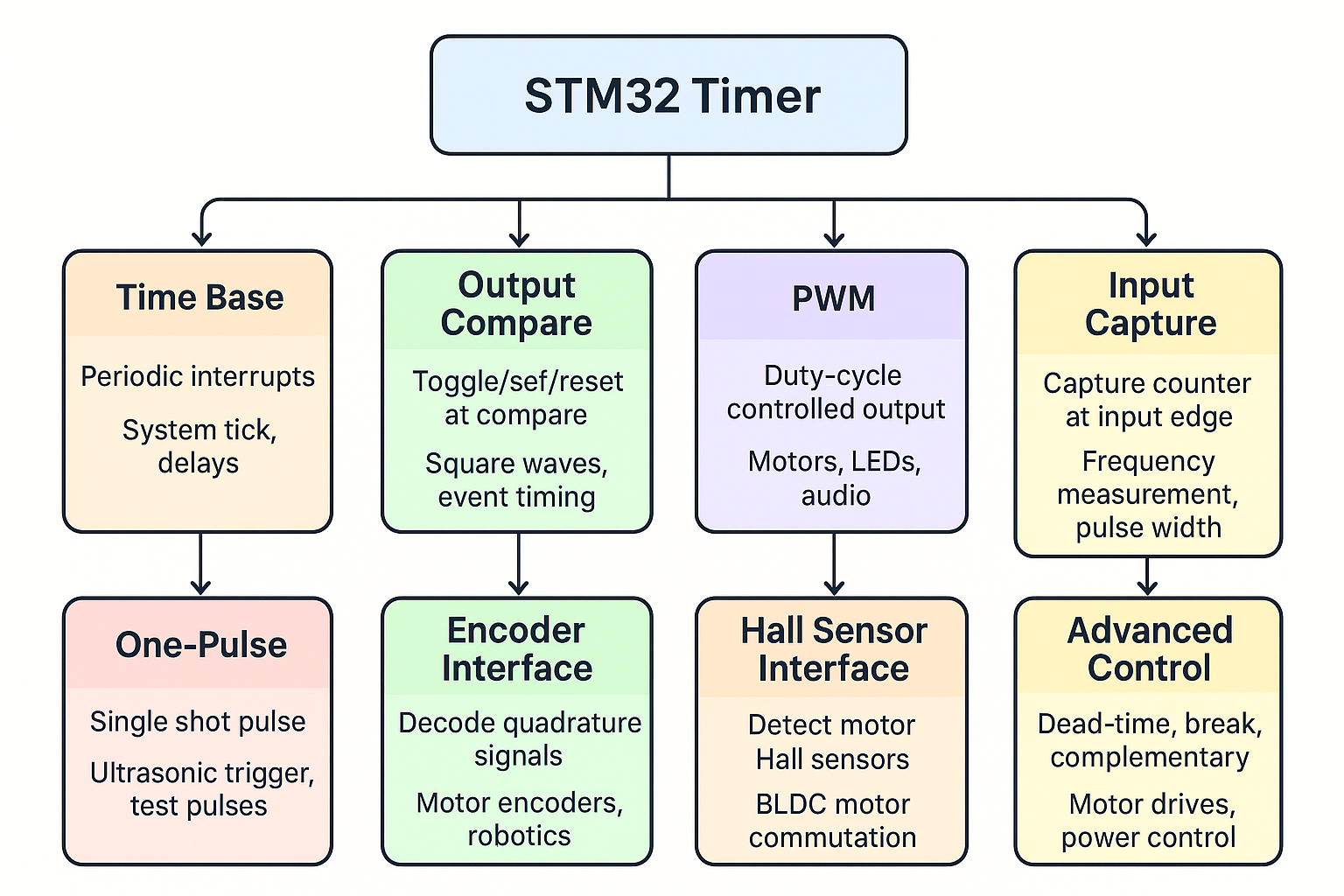
- Time Base Mode (a.k.a. “Up/Down Counter Mode”)
- What it does:
- Timer just counts (up, down, or center-aligned).
- Generates an interrupt when it overflows (ARR reached).
- When to use:
- Create delays.
- Periodic interrupts (e.g., 1 ms tick for an RTOS).
- Trigger other peripherals (ADC, DAC).
 (Source: visualgdb.com)
- What it does:
- Output Compare Mode (OC)
- What it does:
- Compares counter value with CCRx register.
- At a match, an action happens on the output pin (toggle, set, reset).
- When to use:
- Generate square waves without CPU overhead.
- Precise event timing (e.g., toggle pin every 10 µs).
- Create multiple output events from the same timer.
- What it does:
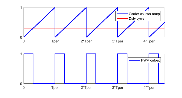
- PWM Mode (Pulse Width Modulation)
- What it does:
- Special case of Output Compare.
- Pin stays HIGH until counter == CCRx, then goes LOW (or vice versa).
- When to use:
- Control motor speed (DC, BLDC).
- Control LED brightness.
- Generate audio, communication pulses (e.g., IR remote signals).
 (Source: mathworks.com)
- What it does:
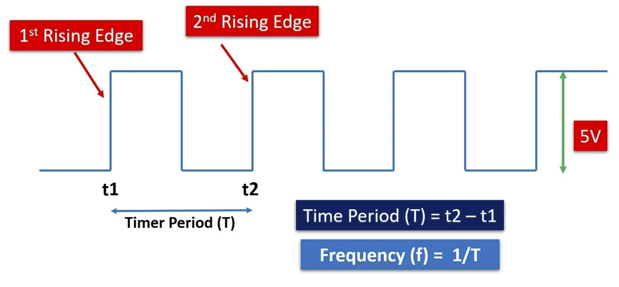
- Input Capture Mode (IC)
- What it does:
- Captures the timer counter value when an input edge occurs.
- When to use:
- Measure signal frequency (time between rising edges).
- Measure pulse width (e.g., ultrasonic sensor echo).
- Decode protocols where timing matters (IR remote, PWM input).
 (Source: microcontrollerslab.com)
- What it does:
- One-Pulse Mode (OPM)
- What it does:
- Timer generates a single output pulse when triggered.
- When to use:
- Generate a precise single trigger pulse.
- Ultrasonic sensor (send one “ping”).
- Test equipment (precise timed pulse).
- What it does:
- Encoder Interface Mode
- What it does:
- Timer is configured to read two quadrature signals (A/B) from a rotary encoder.
- Counter increases/decreases depending on rotation direction.
- When to use:
- Read position/speed of rotary encoders.
- Motor control (servo/BLDC).
- Robotics (wheel encoders for odometry).
- What it does:
- Hall Sensor Interface Mode
- What it does:
- Specialized mode (on advanced timers) for reading 3-phase Hall sensors in motors.
- When to use:
- BLDC motor commutation.
- What it does:
- Advanced Control Features (TIM1, TIM8 only)
- Features:
- Dead-time Insertion: Prevents shoot-through in MOSFET half-bridges.
- Complementary PWM: Outputs PWM with inverted phases.
- Break Input: Emergency stop if something goes wrong.
- When to use:
- Motor drives (inverters, BLDC, PMSM).
- Power electronics (DC-DC converters, UPS).
- Features:
Slave Modes (how the timer is controlled or triggered)
A timer operating in a slave mode does not simply count on its own. Instead, its behavior (starting, stopping, resetting, or operating as an external clock) is dictated by an external trigger signal, which comes from a “Trigger Source” (as shown in the line below “Slave Mode”).
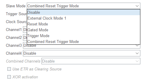
When you open CubeMX and select Slave Mode, you see options like:
- Disabled
- Timer runs normally, free-running with PSC/ARR.
- Reset Mode
- Counter is reset whenever a trigger input occurs.
- Use case: Measure time between external events (e.g., stopwatch resets on each external pulse).
- Gated Mode
- Timer counts only while the trigger input is active (high).
- Use case: Measure pulse width (counter runs only while input is high).
- Trigger Mode
- Timer starts counting on a trigger event (instead of always running).
- Use case: One-shot measurements, synchronized timing between peripherals.
- External Clock Mode 1
- Counter increments using an external signal (instead of internal clock).
- Use case: Count external pulses (e.g., how many pulses from a sensor in 1s).
- Encoder Mode
- Special wiring of two inputs for quadrature encoder signals.
- Use case: Read motor encoder position/direction.
How to Link “Functional Modes” and “CubeMX Options”
Think of it like this:
- First, choose the functional mode:
- Do you want PWM? Input Capture? Encoder? Output Compare?
- Then, choose the slave mode (trigger behavior):
- Does the timer run freely?
- Or should it start/reset/gate based on another signal or timer?
Example:
You want to measure the width of a PWM input signal.
- Functional mode: Input Capture
- Slave mode: Gated mode (counter runs only while signal is HIGH)
Timer modes summary
Here is a kind of summary table (?) I would say the highlighted ones are most relevant to this course, but depending on your project, you might want to choose a non-highlighted mode as well.
| Functional Mode | Typical Slave Mode (CubeMX) | What It Means | Example Use Case |
|---|---|---|---|
| Time Base (periodic interrupt) | Disabled | Timer runs freely with PSC/ARR | Blink LED, RTOS tick, periodic ADC trigger |
| Output Compare | Disabled / Reset Mode | Toggle/Set pin on compare. Reset mode resets counter on external event | Square wave generation, synchronized pulses |
| PWM | Disabled | Counter runs freely, CCR defines duty | LED dimming, motor speed control |
| PWM (synchronized) | Trigger Mode / Reset Mode | PWM starts/reset on master trigger | Multi-phase PWM for motor drives, DAC sync |
| Input Capture (frequency measurement) | Reset Mode | Counter resets on each input edge, capture value gives period | Measure frequency of external signal |
| Input Capture (pulse width measurement) | Gated Mode | Counter runs only while signal is HIGH, captured value = pulse width | Ultrasonic sensor echo timing, PWM input decoding |
| Input Capture (event timestamp) | Trigger Mode | Capture timer value at external event, counter runs continuously | Timestamp external events, protocol decoding |
| One-Pulse Mode | Trigger Mode | Timer generates one pulse when triggered | Ultrasonic trigger pulse, precise test pulses |
| External Clock Mode | External Clock Mode 1 | Timer counts based on external pulses | Count rotations, events, or sensor ticks |
| Encoder Interface | Encoder Mode (TI1, TI2, TI1+TI2) | Timer counts quadrature encoder signals | Motor shaft position/speed measurement |
| Hall Sensor Interface | Encoder Mode (special config) | Works with 3-phase Hall sensors | BLDC motor commutation |
| Advanced PWM (motor control) | Trigger/Reset + Break Input | PWM sync, dead-time, emergency stop | 3-phase inverter, PMSM/BLDC drives |
Any timers current value can be found in TIMx_CNT register.
Master/Slave Synchronization (linking timers together)
Timers can work together:
- One timer = master (produces trigger event)
- Another = slave (starts, resets, or gates counting based on master)
This lets you build complex waveforms, synchronized ADC sampling, or cascaded timers.
Examples:
- TIM1 generates PWM, TIM2 resets every PWM cycle -> TIM2 measures PWM duty timing.
- TIM6 runs as DAC trigger, TIM7 delays another event.
Exercise (Home/Lab): Measure time and print
In this exercise we will learn how to measure the time of events and print the elapsed time on the terminal. In fact, this exercise will make more sense after Lecture-7 since we are using serial print. However, we can give a try to set up UART without going into details yet.
- Create a new project without using the default mode.
- On the left, go to
System Core > RCC > HSE: Crystal/Ceramic Resonator. - Set
TIM2 > Clock source > Internal clockso that we use the HCLK. Also change the prescaler in the configurations. Set it to 108 - 1 as shown in the figure below.
- Go to
Connectivity > USART3 > Mode > Asynchronous.- In this exercise, we will print something on the screen. Therefore, we use UART for only visualization. We will learn more about it later in Lecture 7 - UART: Universal Asynchronous Read and Write.
- Replace PB10->PD8 and PB11->PD9 by dragging the pin while holding Ctrl.
- Make sure the clock configurations look like this:
- Give a good name to your project, do the necessary project settings and generate the code.
- Create a
platformio.inifile in your project and paste the following content in it.[env:nucleo_f767zi] platform = ststm32 board = nucleo_f767zi framework = stm32cube build_flags = -IInc upload_protocol = stlink debug_tool = stlink debug_build_flags = -O0 -g -ggdb monitor_speed = 115200 - Paste this code after
/* USER CODE BEGIN Includes */#include<string.h> // for strlen() #include<stdio.h> // for sprintf() - Paste this code after
/* USER CODE BEGIN 1 */char uart_buf[50]; int uart_buf_len; uint16_t timer_val; - Paste this code after
/* USER CODE BEGIN 2 */// Initial text on the screen uart_buf_len = sprintf(uart_buf, "Timer Test\r\n"); HAL_UART_Transmit(&huart3, (uint8_t *)uart_buf, uart_buf_len, 100); // Start timer HAL_TIM_Base_Start(&htim2); - Paste this code after
/* USER CODE BEGIN 3 */// Get current time (microseconds) timer_val = __HAL_TIM_GET_COUNTER(&htim16); // Wait for 50 ms HAL_GPIO_WritePin(GPIOA, GPIO_PIN_5, GPIO_PIN_SET); HAL_Delay(50); HAL_GPIO_WritePin(GPIOA, GPIO_PIN_5, GPIO_PIN_RESET); // Get time elapsed timer_val = __HAL_TIM_GET_COUNTER(&htim16) - timer_val; // Show elapsed time uart_buf_len = sprintf(uart_buf, "%u us\r\n", timer_val); // unfortunately there is no str() func. in C. HAL_UART_Transmit(&huart2, (uint8_t *)uart_buf, uart_buf_len, 100); // Wait again so we don't flood the Serial terminal HAL_Delay(1000);
This exercise is taken from www.digikey.com. Check it out if you want to learn more in depth. However, pay attention that the board is different than the one we use.