Lecture 9 - I2C (Inter-Integrated Circuit)
The majority of this tutorial is based on these two tutorials: 1) Sparkfun Learn and 2) Geeksforgeeks. All the theory relevant to the exam is in this website, but you can visit the original tutorials to learn more about I2C.
What is I2C?
I2C stands for Inter-Integrated Circuit. It is a bus interface connection protocol incorporated into devices for serial communication. It was originally designed by Philips Semiconductor in 1982. Recently, it is a widely used protocol for short-distance communication. It is also known as Two Wired Interface(TWI).
It is intended to allow multiple “peripheral” digital integrated circuits (“chips”) to communicate with one or more “controller” chips. Like the Serial Peripheral Interface (SPI), it is only intended for short distance communications within a single device. Like Asynchronous Serial Interfaces (such as RS-232 or UARTs), it only requires two signal wires to exchange information.
 (Source: geeksforgeeks.org)
Why don’t we just use UART?
Because serial ports are asynchronous (no clock data is transmitted), devices using them must agree ahead of time on a data rate. The two devices must also have clocks that are close to the same rate, and will remain so–excessive differences between clock rates on either end will cause garbled data.
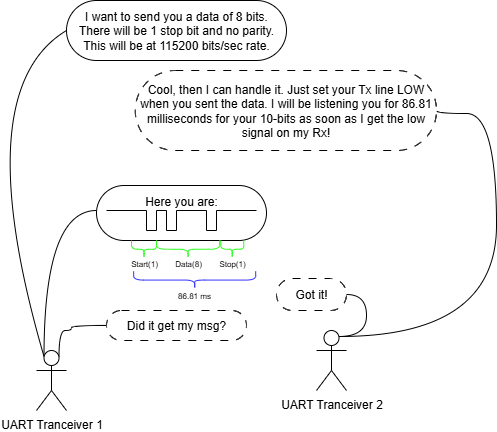
There are some issues with this. First, the UART Transceiver 1 heard nothing from Transceiver 2 because there is not really an acknowledgement procedure. It went well in this scenario, but it doesn’t seem like it will in every case. Here is a more realistic one:
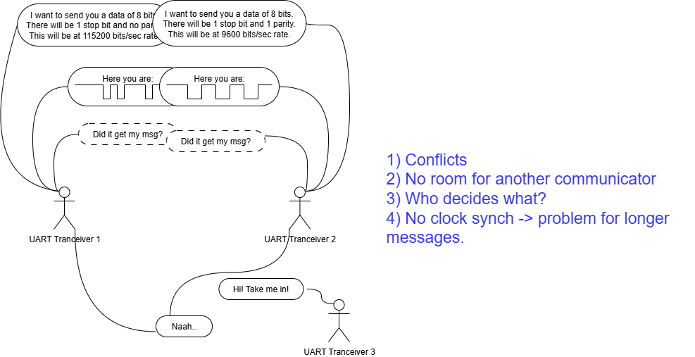
There are some issues:
1) Conflicts in the communication 2) No room for another communicator 3) Who decides what? 4) No clock synch -> problem for longer messages.
In the Transceiver 2’s signal, one bit takes a bit longer. Can you calculate it how long does it take for it to send 1 bit by the way??
What is going on in the background of I2C then?
First and foremost, there is a master-slave structure. Although, this terminology started bothering many people in 2010s and found to be extremely politically incorrect, and tried to be replaced to “controller-peripheral” or “main-secondary” or “initiator-responder”, there is not a consensus for an alternative to master-slave yet, I will continue calling those nodes as their original names.
So the master decides the communication speed, data package size, who is going to send what and when etc. This allows more regulated, reliable and inclusive communication protocol. Yes, third wheels are welcomed!
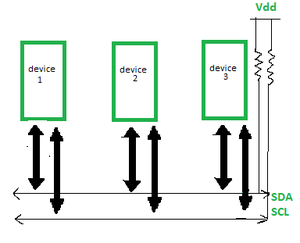
Another big difference that there is a clock signal. It is sent through the SCL line. It is a HIGH signal in default and starts oscillating at a predefined rate. It is either 100 kHz at standard mode or 400 kHz at fast mode.
SDA line, on the other hand, is the line that everyone uses. Master asks for a data from a slave, and the slave sends its response from the same line. All slaves use the same line. You may imagine that the speed of communication reduces drastically as you add mode nodes to I2C.
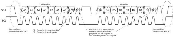
The data is transmitted in the form of packets which comprises 9 bits. The sequence of these bits are:
- Start Condition: 1 bit
- Slave Address: 8 bit
- Acknowledge: 1 bit
This allows that both the master and slaves know whether the message is received or not.
Last, but not least, the data package consists of two main parts: Address and Data.
 (Source: learn.sparkfun.com)
START condition plus address packet plus one more data packet plus STOP condition collectively form a complete Data transfer.
The address can be found in the datasheet of the device. It can be:
- Who-Am-I address: “I2C Who Am I” is a term for a command or register that allows a device on an I2C bus to identify itself. It’s a way for a master to confirm it’s communicating with the correct device by reading a specific, read-only register that holds the device’s unique ID. To use it, you first need to know the I2C address of the slave device to communicate with it, and then send a command to read its “Who Am I” register.
- Address of a data which is stored in the device.
Let’s learn more about it through an exercise.
Exercise: Accelerometer reading from MMA8451
What is an accelerometer?
An accelerometer is a device that measures, well, acceleration. There are two main use-cases of an accelerometer:
- If there is a motion on the object where the accelerometer fastly attached, then you can measure the acceleration of this object. Remember from your physics class: if you integrate acceleration, you will get velocity. If you integrate the velocity, you will get position. Therefore, accelerometers are useful in positioning and localization problems in robotics. Althought GPS is more often used in localization, it fails in indoor applications. Today, all the smartphones, electrical cars and mobile robots have either a standalone accelerometer, or a device called IMU (inertial measurement unit) which contains an accelerometer in.
- If there is not a motion, there is still an acceleration we all feel all the time: GRAVITY. It is around 9.8 m/s^2 on Earth although this number is slightly higher if you are closer to the North/South pole (~9.83 m/s^2) or slightly lower if you are closer to Ecuator (~9.78 m/s^2). The gravity allow us to calculate “tilt” angles.
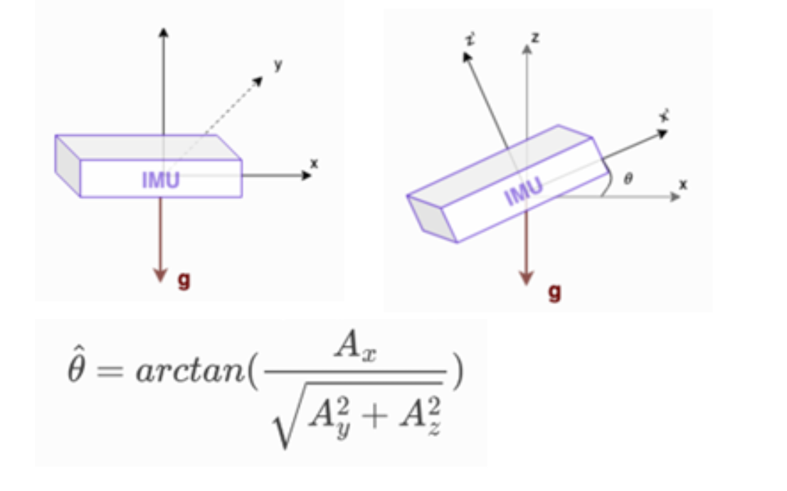
The figure above shows how the tilt angle in one direction can be calculated using gravity. On the figure left, as the accelerometer stays horizontal, the gravity is only on the z-axis. Therefore we would read from accelerometer something like this: ax= 0.0 ay= 0.0 ax= -9.81. If we tilt the accelerometer a bit, let’s say \(\theta\) degrees counter-clockwise about the y-axis (y axis is toward the screen if you calculate). Then we start reading some values both on z and x axes. Maybe something like this: ax= -6.94 ay= 0.0 ax= -6.94 if \(\theta = 45\) degrees. Obs that \(a_x^2 + a_y^2 = 9.81^2\)
Although the mathematical calculation is not necessary for this course, you should be able to calculate it as an engineer.
STM32CubeMX setup
In this exercise we will configure I2C1 as the Master to communicate with the MMA8451 and USART3 to send data to the PC (via the ST-LINK virtual COM port).
- Create a new project targeting the STM32F767ZI without using the default mode.
- On the left, go to
System Core > RCC > HSE: Crystal/Ceramic Resonator. - Set
PB0(pin connected to LD1) asGPIO_Outputand change its label toLD1. - Under “Pinout & Configuration,” go to Connectivity >
I2C1. - I2C Settings:
- Set the it to
I2Cmode. This will automatically assign PB6 asI2C1_SCLand PB7 asI2C1_SDA. However, for easily accessing the pins through the headers, move these pins toPB8andPB9, which will be theD15andD14onCN7header. - Under I2C configuration, set the
I2C Speed Modeto Fast Mode, which will set the frequency to 400 automatically. - Leave I2C Adressing Mode as 7-bit.
- In the
NVICSettings tab, ensure theI2C1global interrupt is disabled. We will use polling/blocking I2C functions for simplicity, but interrupts can be used for non-blocking communication.
- Set the it to
- UART Settings:
- Under “Pinout & Configuration,” go to Connectivity > USART3. This is the UART that will make the board communicate with its PC via serial monitor.
- Set the Mode to Asynchronous.
- Change the default RX and TX pins to PD8 (TX) and PD9 (RX) since they are connected to our STLINK.
- In the Parameter Settings tab:
- Set the Baud Rate to 115200 (This is a common, reliable speed).
- Leave Word Length at 8 Bits, Parity at None, and Stop Bits at 1.
- In the
NVICSettings tab, ensure theUSART3global interrupt is disabled. We will use polling/blocking UART functions for simplicity, but interrupts can be used for non-blocking communication.
- Clock Configuration and Code Generation:
- Set your clock configurations with 8 MHz Input frequency, PLLCLK in system clock MUX, and HCLK = 108 MHz
- Give a proper name and generate the code as usual: Basic application structure, STM32CubeIDE Toolchain, untick “Generate under root” and generate the code.
Hardware setup
The I2C communication requires minimal wiring.
- Connect SCL: STM32F767 PB8 (I2C1_SCL) → MMA8451 SCL
- Connect SDA: STM32F767 PB9 (I2C1_SDA) → MMA8451 SDA
- Power: Connect the STM32’s VCC (3.3V) → MMA8451 VCC
- Ground: Connect the STM32’s GND → MMA8451 GND
Note on Pull-ups:
I2C requires pull-up resistors on the SCL and SDA lines. Most MMA8451 breakout boards already include them. If yours does not, you must add 4.7 kΩ pull-up resistors to 3.3V on both lines. If you don’t have 4.7 kΩ in your box, then use 10 kΩ. HOWEVER, the module has those pull-up resistors already attached as you can see in the module’s datasheet. THEREFORE, YOU DON’T NEED THE PULL-UP RESISTORS FOR THIS MODULE.
Code implementation
- Here is your platformio.ini:
[env:nucleo_f767zi] platform = ststm32 board = nucleo_f767zi framework = stm32cube build_flags = -IInc -Wl,--undefined,_printf_float upload_protocol = stlink debug_tool = stlink monitor_speed = 115200 ; Set the baud rate for the serial monitor debug_build_flags = -O0 -g -ggdb - First add
#include<stdio.h>and#include<string.h>in/* USER CODE BEGIN Includes */forsprintf()andstrlen(). -
We need to initialize the MMA8451 (set it to active mode) and then continuously read the acceleration data. In
main.c, under/* USER CODE BEGIN PV */, define the I2C address and relevant registers. We know these addresses from the MMA8451 datasheet. Additionally, according to the Adafruit documentation, the A pin is pulled up to 3.3V with a 10 kΩ resistor by default. This sets the I2C 7-bit address to 0x1D. If you connect the A pin to GND, the address becomes 0x1C.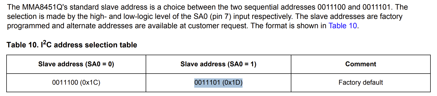
#define MMA8451_ADDRESS (0x1D << 1) // 8-bit I2C Slave Address (0x3A) #define MMA8451_WHO_AM_I_REG 0x0D // WHO_AM_I Register: expected value 0x1A #define MMA8451_CTRL_REG1 0x2A // Control Register 1 #define MMA8451_XYZ_DATA_CFG 0x0E // Data Configuration Register #define MMA8451_OUT_X_MSB 0x01 // First data register for X-axis MSB int16_t Accel_X, Accel_Y, Accel_Z; // 14-bit data will fit in 16-bit signed integer uint8_t RxData[6]; // Buffer to store X, Y, Z data (2 bytes per axis) char TxBuffer[100]; // Buffer for UART output -
We will create
MMA8451_Init()function in the next step. Since it is defined after themain.c, in the C language we must define a function prototype before the main. Put this in/* USER CODE BEGIN PFP */void MMA8451_Init(void); -
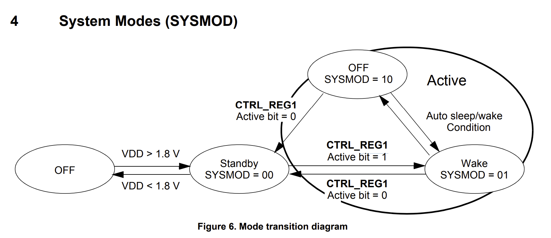
MMA8451 Initialization Function: We will create a function to configure the accelerometer. The core steps are: standby mode \(\rightarrow\) configure \(\rightarrow\) active mode. In
main.c, under/* USER CODE BEGIN 4 */implement the initialization function. These are necessary to configure the accelerometer.void MMA8451_Init(void) { uint8_t Data; // 1. Standby Mode: Clear Active bit (Bit 0) in CTRL_REG1 Data = 0x00; HAL_I2C_Mem_Write(&hi2c1, MMA8451_ADDRESS, MMA8451_CTRL_REG1, 1, &Data, 1, HAL_MAX_DELAY); // 2. Configure: Set Scale (2g range) in XYZ_DATA_CFG Data = 0x00; // Full Scale 2g (bits Fs1:Fs0 = 00) HAL_I2C_Mem_Write(&hi2c1, MMA8451_ADDRESS, MMA8451_XYZ_DATA_CFG, 1, &Data, 1, HAL_MAX_DELAY); // 3. Active Mode: Set Active bit (Bit 0) in CTRL_REG1 Data = 0x01; // ODR=800Hz (default), Active Mode (Bit 0 = 1) HAL_I2C_Mem_Write(&hi2c1, MMA8451_ADDRESS, MMA8451_CTRL_REG1, 1, &Data, 1, HAL_MAX_DELAY); }This function is purely device specific and quite advanced in terms of reading datasheet, bit manipulation etc. While it is definitely beneficial to understand what is going on if you consider a job related to embedded systems in the future, it is not relevan to the exam. You are NOT expected to be able to write addresses and know the whole I2C sequence of MMA8451 in the exam.
-
Call the initialization function in the main function under
/* USER CODE BEGIN 2 */.// Initialize the MMA8451 MMA8451_Init(); // Optional: Check WHO_AM_I register to confirm communication is working uint8_t who_am_i; HAL_I2C_Mem_Read(&hi2c1, MMA8451_ADDRESS, MMA8451_WHO_AM_I_REG, 1, &who_am_i, 1, HAL_MAX_DELAY); if (who_am_i == 0x1A) { // Communication established! Toggle LED to confirm. HAL_GPIO_TogglePin(LD1_GPIO_Port, LD1_Pin); } -
In the main while(1) loop, under
/* USER CODE BEGIN 3 */, add the code to read the X, Y, Z acceleration data, process it, and transmit it via UART.// 1. Read 6 bytes of acceleration data (X MSB, X LSB, Y MSB, Y LSB, Z MSB, Z LSB) // Start reading from OUT_X_MSB (0x01) HAL_I2C_Mem_Read(&hi2c1, MMA8451_ADDRESS, MMA8451_OUT_X_MSB, 1, RxData, 6, HAL_MAX_DELAY); // 2. Process the 14-bit data. The data is Left-Justified. // We need to shift the MSB left by 8 and combine with the LSB, then right-shift by 2 to align. Accel_X = (int16_t)((RxData[0] << 8) | RxData[1]) >> 2; Accel_Y = (int16_t)((RxData[2] << 8) | RxData[3]) >> 2; Accel_Z = (int16_t)((RxData[4] << 8) | RxData[5]) >> 2; // 3. Convert raw values to human-readable string (using standard library function) // The raw 14-bit value corresponds to acceleration in g's. // Raw Value * (2g / 8192) will give acceleration in g's. int len = sprintf(TxBuffer, "X: %d, Y: %d, Z: %d\r\n", Accel_X, Accel_Y, Accel_Z); // 4. Transmit the data via USART3 to the serial monitor HAL_UART_Transmit(&huart3, (uint8_t *)TxBuffer, len, HAL_MAX_DELAY); // 5. Wait for half a second before sending the next message HAL_Delay(500); - Build and upload.
Note that if the LD1 is ON, then the I2C communication is correct. If not, check your connections and pin configurations.
Interpreting the data
Currently the data you are reading is something like this: X: 522, Y: 44, Z: 4090 But what does it mean?
The MMA8451 is a 14-bit sensor. When configured for the ±2g range (which you set with Data = 0x00 in MMA8451_Init), the maximum positive reading (FS, or Full Scale) corresponds to 2g, and the maximum negative reading corresponds to -2g. The raw 14-bit output ranges from -8192 (negative full scale) to +8191 (positive full scale).
So what you are reading at z-axis which is close to \(8192/2=4096\) is in fact 1g (aka 1 g-force):)
At this point, you should be able to calculate this: if 14-bits data (decimal up to 8191 since it is signed value) is 2g, what is 4090 in g? or more generic if 14-bits data (decimal up to 8191) is 2g, what is ax, ay and az values in g?
If you can calculate it, good for you! It is the same principle of mapping like we did in ADC lecture if 10-bits data (decimal up to 1023 for unsigned value) is 3.3v, what is the adc_val in voltage?. Or similarly what we did for servo control if 4000 ticks equal to 180 degrees, how many ticks are required to set the servo to 75 degrees?
I hope you are convinced that all these calculations stems from the same principle: ratio and proportion of two linked variables.
Can you modify the code such that you will see (In two separate lines)
c
    X: 514, Y: 16, Z: 4096
    X: 0.13, Y: 0.00, Z: 1.00
If you still cannot solve it, continue reading:
The conversion formula is:
\[\text{g-Force} = \text{Raw Value} \times \frac{\text{Selected Range} (\text{in } \text{g})}{\text{Max Raw Count}}\]where selected Range is \(2\text{g}\). Max Raw Count is \(2^{13} = 8192\). (Since the data is signed 14-bit, 1 bit is the sign, leaving 13 bits for magnitude).
You’ll need three float variables for the final g-force values. This code should be placed in your while(1) loop, after calculating Accel_X, Accel_Y, and Accel_Z. I will place it after the first HAL_UART_Transmit() where the raw data is transmitted.
Also you should modify where you transmit data via UART to something like this:
// ...
// Whis is where you send original raw data
int len = sprintf(TxBuffer, "X: %d, Y: %d, Z: %d\r\n", Accel_X, Accel_Y, Accel_Z);
HAL_UART_Transmit(&huart3, (uint8_t *)TxBuffer, len, HAL_MAX_DELAY);

// 4. Converted to g values
// Conversion to g-force values (in g's)
// Define constants for the conversion (2g range / 8192 counts)
// These would have been better with the other private defines at the beginning of the code, though.
#define ACCEL_RANGE_G 2.0f
#define ACCEL_MAX_RAW 8192.0f

// Also these would have been better outside of the loop.
float Accel_X_g, Accel_Y_g, Accel_Z_g;

Accel_X_g = ((float)Accel_X / ACCEL_MAX_RAW) * ACCEL_RANGE_G; // e.g., Raw/8192 * 2g
Accel_Y_g = ((float)Accel_Y / ACCEL_MAX_RAW) * ACCEL_RANGE_G;
Accel_Z_g = ((float)Accel_Z / ACCEL_MAX_RAW) * ACCEL_RANGE_G;
int len2 = sprintf(TxBuffer, "X: %.2f, Y: %.2f, Z: %.2f\r\n", Accel_X_g, Accel_Y_g, Accel_Z_g);
HAL_UART_Transmit(&huart3, (uint8_t *)TxBuffer, len2, HAL_MAX_DELAY);