IP Address Part 2
MAC Address
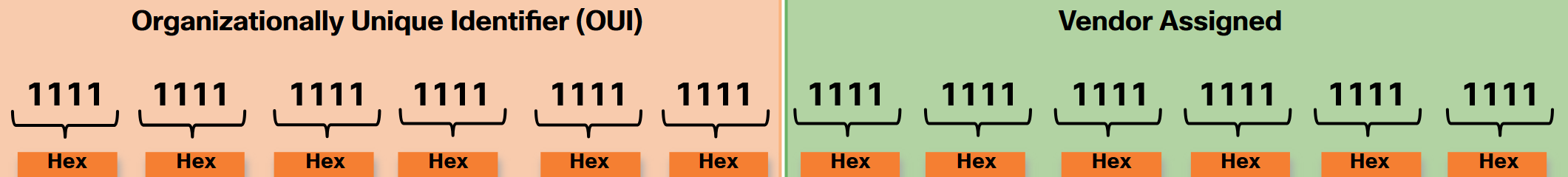
An Ethernet MAC address consists of a 48-bit binary value. Hexadecimal is used to identify an Ethernet address because a single hexadecimal digit represents four binary bits. Therefore, a 48-bit Ethernet MAC address can be expressed using only 12 hexadecimal values. The MAC address is used to identify the physical source and destination devices (NICs) on the local network segment. MAC addressing provides a method for device identification at the data link layer of the OSI model. All MAC addresses must be unique to the Ethernet device or Ethernet interface. To ensure this, all vendors that sell Ethernet devices must register with the IEEE to obtain a unique 6 hexadecimal (i.e., 24-bit or 3-byte) code called the organizationally unique identifier (OUI). Institute of Electrical and Electronics Engineers (IEEE) is an organization of electrical engineering and electronics dedicated to advancing technological innovation and creating standards in a wide area of industries including power and energy, healthcare, telecommunications, and networking. Important IEEE networking standards include 802.3 Ethernet and 802.11 WLAN standard. When a vendor assigns a MAC address to a device or Ethernet interface, the vendor must do as follows:
- Use its assigned OUI as the first 6 hexadecimal digits.
- Assign a unique value in the last 6 hexadecimal digits.
Therefore, an Ethernet MAC address consists of a 6 hexadecimal vendor OUI code followed by a 6 hexadecimal vendor-assigned value, as shown in the figure.
For example, assume that Cisco needs to assign a unique MAC address to a new device. The IEEE has assigned Cisco a OUI of 00-60-2F. Cisco would then configure the device with a unique vendor code such as 3A-07-BC. Therefore, the Ethernet MAC address of that device would be 00-60-2F-3A-07-BC. It is the responsibility of the vendor to ensure that none of its devices be assigned the same MAC address. However, it is possible for duplicate MAC addresses to exist because of mistakes made during manufacturing, mistakes made in some virtual machine implementation methods, or modifications made using one of several software tools. In any case, it will be necessary to modify the MAC address with a new NIC or make modifications via software. Sometimes the MAC address is referred to as a burned-in address (BIA) because the address is hard coded into read-only memory (ROM) on the NIC. This means that the address is encoded into the ROM chip permanently. Note: On modern PC operating systems and NICs, it is possible to change the MAC address in software. This is useful when attempting to gain access to a network that filters based on BIA. Consequently, filtering or controlling traffic based on the MAC address is no longer as secure.
Unicast
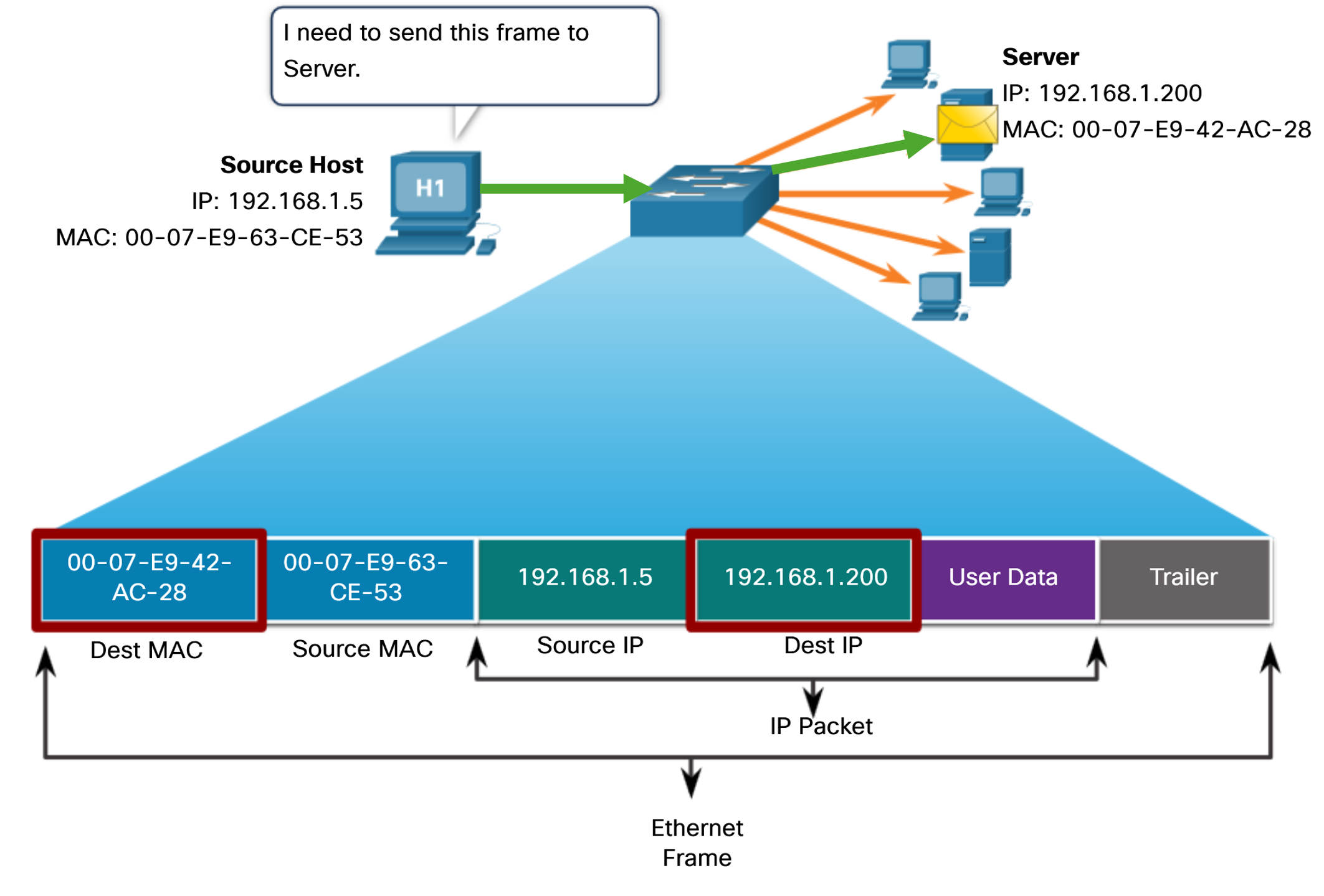
In Ethernet, different MAC addresses are used for Layer 2 unicast, broadcast, and multicast communications. A unicast MAC address is the unique address that is used when a frame is sent from a single transmitting device to a single destination device. For a unicast packet to be sent and received, a destination IP address must be in the IP packet header. A corresponding destination MAC address must also be present in the Ethernet frame header. The IP address and MAC address combine to deliver data to one specific destination host. Note: The source MAC address must always be a unicast.
Broadcast
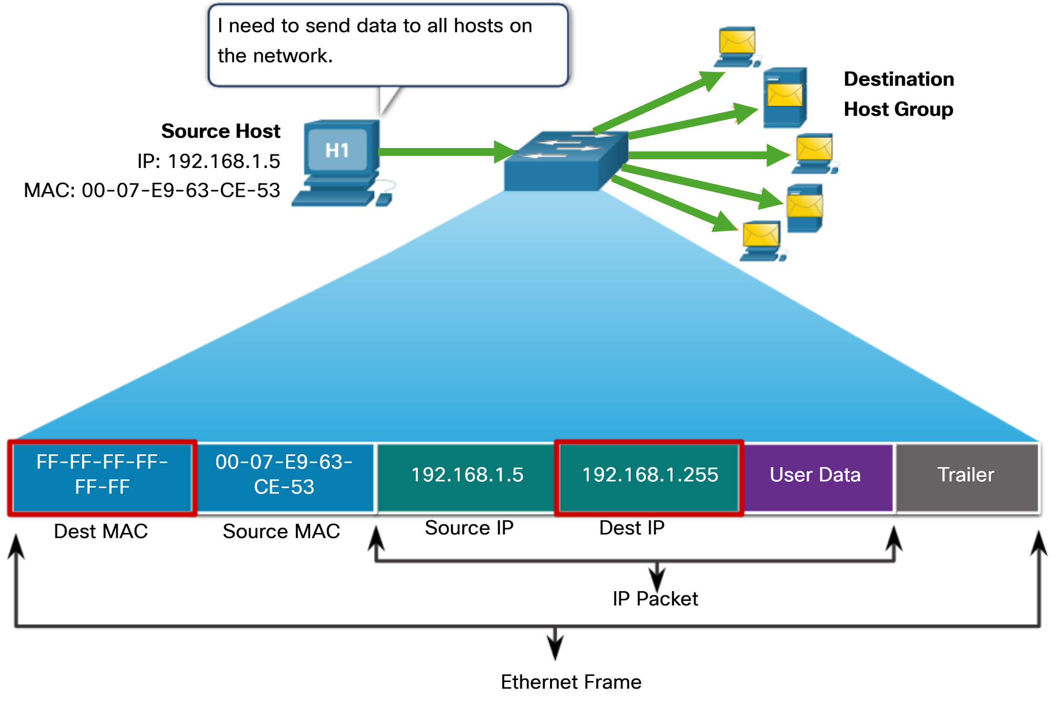
An Ethernet broadcast frame is received and processed by every device on the Ethernet LAN. The features of an Ethernet broadcast are as follows:
- It has a destination MAC address of FF-FF-FF-FF-FF-FF in hexadecimal (48 ones in binary).
- It is flooded out all Ethernet switch ports except the incoming port.
- It is not forwarded by a router.
If the encapsulated data is an IPv4 broadcast packet, this means the packet contains a destination IPv4 address that has all ones (1s) in the host portion. This numbering in the address means that all hosts on that local network (broadcast domain) will receive and process the packet. When the IPv4 broadcast packet is encapsulated in the Ethernet frame, the destination MAC address is the broadcast MAC address of FF-FF-FF-FF-FF-FF in hexadecimal (48 ones in binary). DHCP for IPv4 is an example of a protocol that uses Ethernet and IPv4 broadcast addresses. However, not all Ethernet broadcasts carry an IPv4 broadcast packet. For example, ARP Requests do not use IPv4, but the ARP message is sent as an Ethernet broadcast.
Multicast
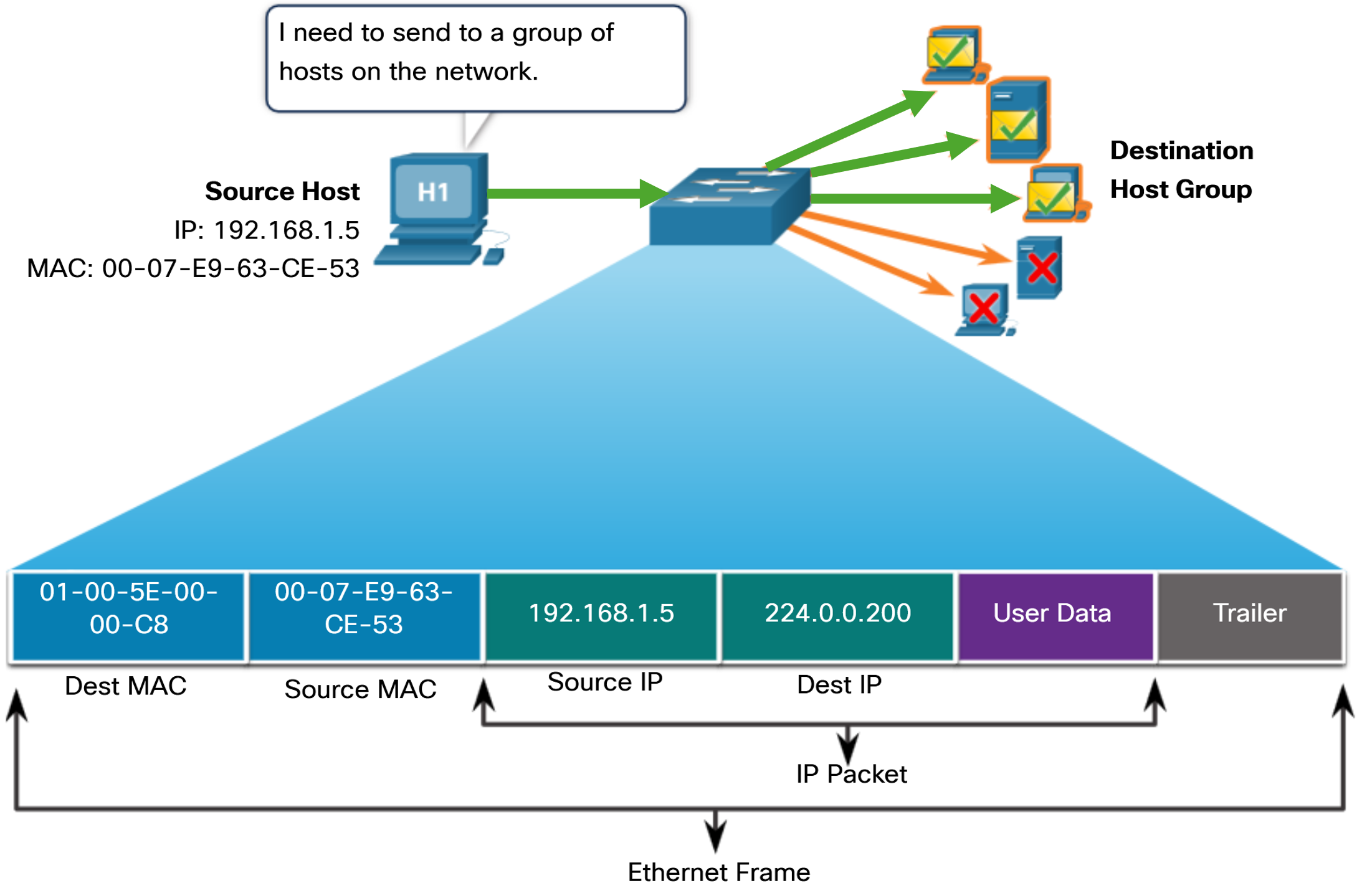
An Ethernet multicast frame is received and processed by a group of devices on the Ethernet LAN that belong to the same multicast group. The features of an Ethernet multicast are as follows:
- There is a destination MAC address of 01-00-5E when the encapsulated data is an IPv4 multicast packet and a destination MAC address of 33-33 when the encapsulated data is an IPv6 multicast packet.
- There are other reserved multicast destination MAC addresses for when the encapsulated data is not IP, such as Spanning Tree Protocol (STP) and Link Layer Discovery Protocol (LLDP).
- It is flooded out all Ethernet switch ports except the incoming port, unless the switch is configured for multicast snooping.
- It is not forwarded by a router, unless the router is configured to route multicast packets.
If the encapsulated data is an IP multicast packet, the devices that belong to a multicast group are assigned a multicast group IP address. Because multicast addresses represent a group of addresses (sometimes called a host group), they can only be used as the destination of a packet. The source will always be a unicast address. As with the unicast and broadcast addresses, the multicast IP address requires a corresponding multicast MAC address to deliver frames on a local network. Routing protocols and other network protocols use multicast addressing.
Address Resolution Protocol (ARP)
If your network is using the IPv4 communications protocol, the Address Resolution Protocol (ARP) is what you need to map IPv4 addresses to MAC addresses. This section explains how ARP works. Every IP device on an Ethernet network has a unique Ethernet MAC address. When a device sends an Ethernet Layer 2 frame, it contains these two addresses:
- Destination MAC address - The Ethernet MAC address of the destination device on the same local network segment. If the destination host is on another network, then the destination address in the frame would be that of the default gateway (i.e., router).
- Source MAC address - The MAC address of the Ethernet NIC on the source host.
To send a packet to another host on the same local IPv4 network, a host must know the IPv4 address and the MAC address of the destination device. Device destination IPv4 addresses are either known or resolved by device name. However, MAC addresses must be discovered. A device uses ARP to determine the destination MAC address of a local device when it knows its IPv4 address. ARP provides two basic functions:
- Resolving IPv4 addresses to MAC addresses
- Maintaining a table of IPv4 to MAC address mappings
ARP Functions
When a packet is sent to the data link layer to be encapsulated into an Ethernet frame, the device refers to a table in its memory to find the MAC address that is mapped to the IPv4 address. This table is stored temporarily in RAM memory and called the ARP table or the ARP cache. The sending device will search its ARP table for a destination IPv4 address and a corresponding MAC address:
- If the packet’s destination IPv4 address is on the same network as the source IPv4 address, the device will search the ARP table for the destination IPv4 address.
- If the destination IPv4 address is on a different network than the source IPv4 address, the device will search the ARP table for the IPv4 address of the default gateway.
In both cases, the search is for an IPv4 address and a corresponding MAC address for the device. Each entry, or row, of the ARP table binds an IPv4 address with a MAC address. We call the relationship between the two values a map. This simply means that you can locate an IPv4 address in the table and discover the corresponding MAC address. The ARP table temporarily saves (caches) the mapping for the devices on the LAN. If the device locates the IPv4 address, its corresponding MAC address is used as the destination MAC address in the frame. If there is no entry is found, then the device sends an ARP request.
ARP Request
An ARP request is sent when a device needs to determine the MAC address that is associated with an IPv4 address, and it does not have an entry for the IPv4 address in its ARP table. ARP messages are encapsulated directly within an Ethernet frame. There is no IPv4 header. The ARP request is encapsulated in an Ethernet frame using the following header information:
- Destination MAC address - This is a broadcast address FF-FF-FF-FF-FF-FF requiring all Ethernet NICs on the LAN to accept and process the ARP request.
- Source MAC address - This is MAC address of the sender of the ARP request.
- Type - ARP messages have a type field of 0x806. This informs the receiving NIC that the data portion of the frame needs to be passed to the ARP process.
Because ARP requests are broadcasts, they are flooded out all ports by the switch, except the receiving port. All Ethernet NICs on the LAN process broadcasts and must deliver the ARP request to its operating system for processing. Every device must process the ARP request to see if the target IPv4 address matches its own. A router will not forward broadcasts out other interfaces. Only one device on the LAN will have an IPv4 address that matches the target IPv4 address in the ARP request. All other devices will not reply.
ARP Reply
Only the device with the target IPv4 address associated with the ARP request will respond with an ARP reply. The ARP reply is encapsulated in an Ethernet frame using the following header information:
- Destination MAC address - This is the MAC address of the sender of the ARP request.
- Source MAC address - This is the MAC address of the sender of the ARP reply.
- Type - ARP messages have a type field of 0x806. This informs the receiving NIC that the data portion of the frame needs to be passed to the ARP process.
Only the device that originally sent the ARP request will receive the unicast ARP reply. After the ARP reply is received, the device will add the IPv4 address and the corresponding MAC address to its ARP table. Packets destined for that IPv4 address can now be encapsulated in frames using its corresponding MAC address. If no device responds to the ARP request, the packet is dropped because a frame cannot be created. Entries in the ARP table are time stamped. If a device does not receive a frame from a particular device before the timestamp expires, the entry for this device is removed from the ARP table. Additionally, static map entries can be entered in an ARP table, but this is rarely done. Static ARP table entries do not expire over time and must be manually removed.
ARP in Remote Communications
When the destination IPv4 address is not on the same network as the source IPv4 address, the source device needs to send the frame to its default gateway. This is the interface of the local router. Whenever a source device has a packet with an IPv4 address on another network, it will encapsulate that packet in a frame using the destination MAC address of the router.
The IPv4 address of the default gateway is stored in the IPv4 configuration of the hosts. When a host creates a packet for a destination, it compares the destination IPv4 address and its own IPv4 address to determine if the two IPv4 addresses are located on the same Layer 3 network. If the destination host is not on its same network, the source checks its ARP table for an entry with the IPv4 address of the default gateway. If there is not an entry, it uses the ARP process to determine a MAC address of the default gateway.
Remove Entries from an ARP Table
For each device, an ARP cache timer removes ARP entries that have not been used for a specified period of time. The times differ depending on the operating system of the device. For example, newer Windows operating systems store ARP table entries between 15 and 45 seconds. Commands may also be used to manually remove some or all of the entries in the ARP table. After an entry has been removed, the process for sending an ARP request and receiving an ARP reply must occur again to enter the map in the ARP table.
ARP Issues
As a broadcast frame, an ARP request is received and processed by every device on the local network. On a typical business network, these broadcasts would probably have minimal impact on network performance. However, if a large number of devices were to be powered up and all start accessing network services at the same time, there could be some reduction in performance for a short period of time, as shown in the figure. After the devices send out the initial ARP broadcasts and have learned the necessary MAC addresses, any impact on the network will be minimized.
In some cases, the use of ARP can lead to a potential security risk. A threat actor can use ARP spoofing to perform an ARP poisoning attack. This is a technique used by a threat actor to reply to an ARP request for an IPv4 address that belongs to another device, such as the default gateway, as shown in the figure. The threat actor sends an ARP reply with its own MAC address. The receiver of the ARP reply will add the wrong MAC address to its ARP table and send these packets to the threat actor.
The MAC Address Table
Now that you know all about Ethernet MAC addresses, it is time to talk about how a switch uses these addresses to forward (or discard) frames to other devices on a network. If a switch just forwarded every frame it received out all ports, your network would be so congested that it would probably come to a complete halt. A Layer 2 Ethernet switch uses Layer 2 MAC addresses to make forwarding decisions. It is completely unaware of the data (protocol) being carried in the data portion of the frame, such as an IPv4 packet or an ARP message. The switch makes its forwarding decisions based solely on the Layer 2 Ethernet MAC addresses. An Ethernet switch examines its MAC address table to make a forwarding decision for each frame, unlike legacy Ethernet hubs that repeat bits out all ports except the incoming port. Note: The MAC address table is sometimes referred to as a content addressable memory (CAM) table. While the term CAM table is fairly common, for the purposes of this course, we will refer to it as a MAC address table.
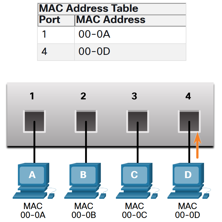
The switch dynamically builds the MAC address table by examining the source MAC address of the frames received on a port. The switch forwards frames by searching for a match between the destination MAC address in the frame and an entry in the MAC address table.
- Examine the Source MAC Address: Every frame that enters a switch is checked for new information to learn. It does this by examining the source MAC address of the frame and the port number where the frame entered the switch. If the source MAC address does not exist, it is added to the table along with the incoming port number. If the source MAC address does exist, the switch updates the refresh timer for that entry in the table. By default, most Ethernet switches keep an entry in the table for 5 minutes. Note: If the source MAC address does exist in the table but on a different port, the switch treats this as a new entry. The entry is replaced using the same MAC address but with the more current port number.
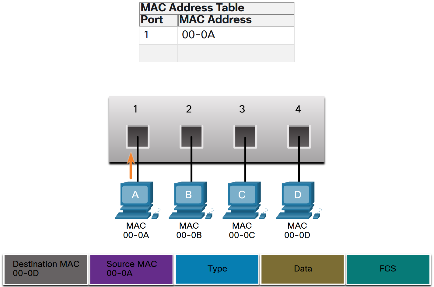
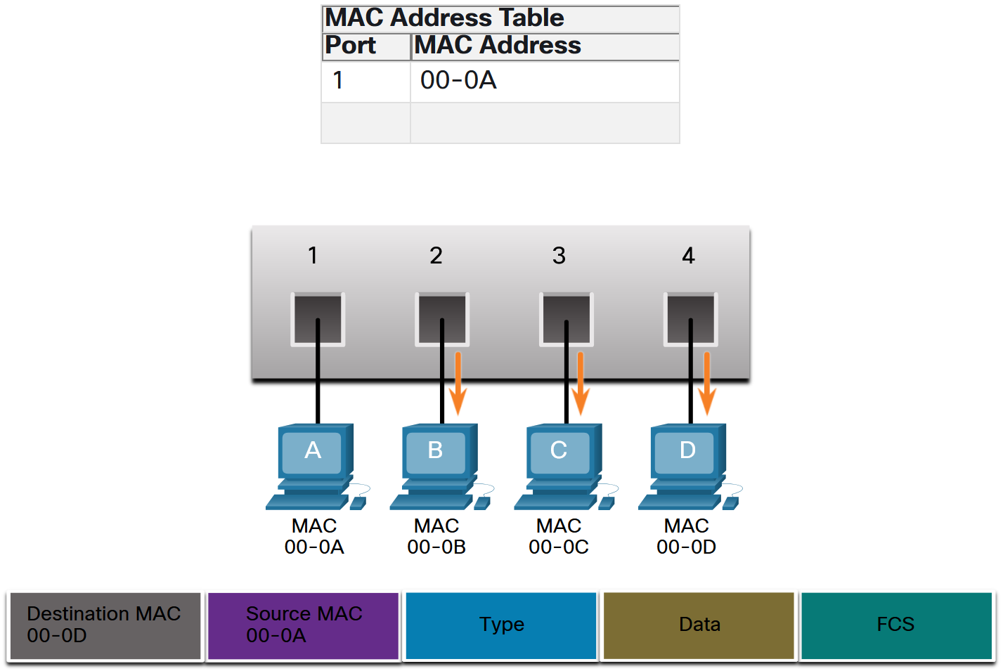
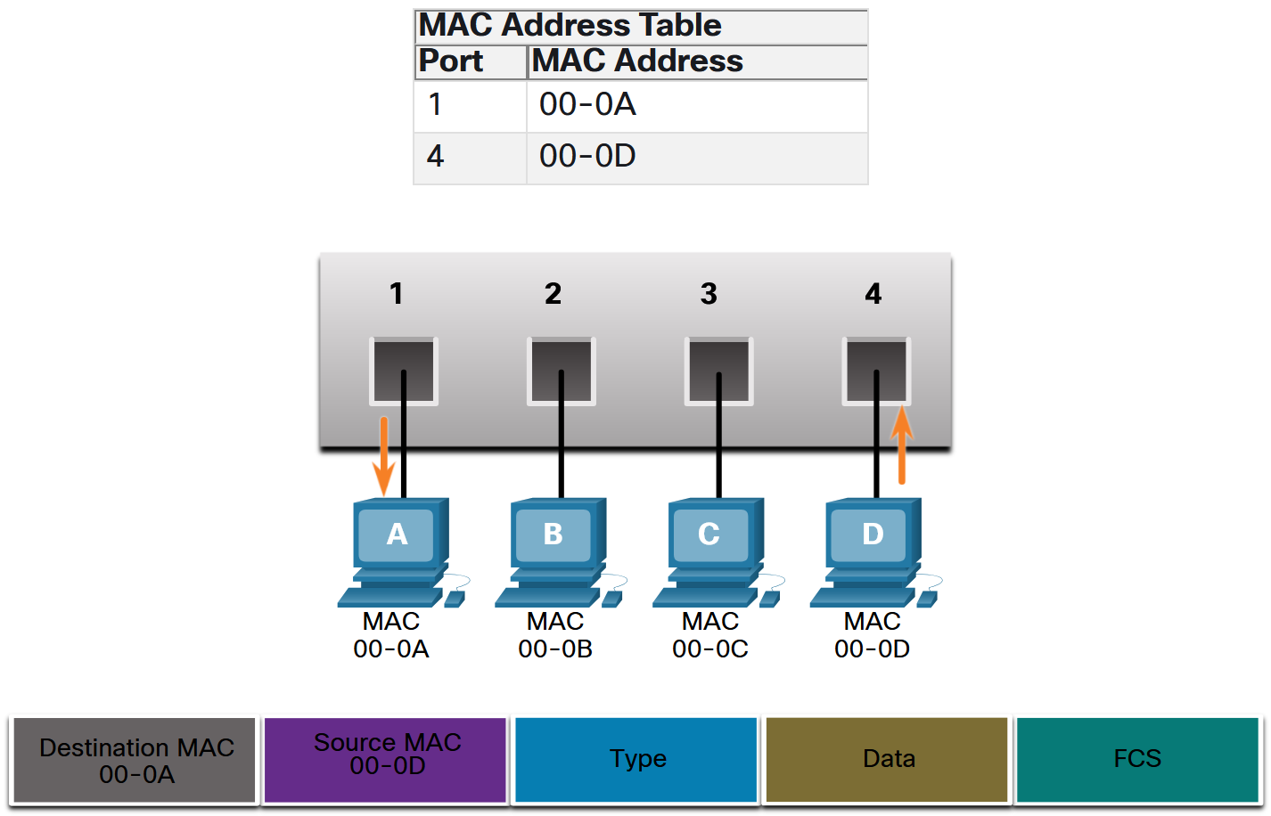
- Find the Destination MAC Address: If the destination MAC address is a unicast address, the switch will look for a match between the destination MAC address of the frame and an entry in its MAC address table. If the destination MAC address is in the table, it will forward the frame out the specified port. If the destination MAC address is not in the table, the switch will forward the frame out all ports except the incoming port. This is called an unknown unicast. Note: If the destination MAC address is a broadcast or a multicast, the frame is also flooded out all ports except the incoming port.
- Filtering Frames: As a switch receives frames from different devices, it is able to populate its MAC address table by examining the source MAC address of every frame. When the MAC address table of the switch contains the destination MAC address, it is able to filter the frame and forward out a single port.
A switch can have multiple MAC addresses associated with a single port. This is common when the switch is connected to another switch. The switch will have a separate MAC address table entry for each frame received with a different source MAC address. When a device has an IP address that is on a remote network, the Ethernet frame cannot be sent directly to the destination device. Instead, the Ethernet frame is sent to the MAC address of the default gateway, the router.
Frame Forwarding Methods on Switches
As you learned in the previous section, switches use their MAC address tables to determine which port to use to forward frames. With Cisco switches, there are actually two frame forwarding methods and there are good reasons to use one instead of the other, depending on the situation. Switches use one of the following forwarding methods for switching data between network ports:
- Store-and-forward switching: This frame forwarding method receives the entire frame and computes the CRC. CRC uses a mathematical formula, based on the number of bits (1s) in the frame, to determine whether the received frame has an error. If the CRC is valid, the switch looks up the destination address, which determines the outgoing interface. Then the frame is forwarded out of the correct port.
- Cut-through switching: This frame forwarding method forwards the frame before it is entirely received. At a minimum, the destination address of the frame must be read before the frame can be forwarded.
Store-and-forward Switching
A big advantage of store-and-forward switching is that it determines if a frame has errors before propagating the frame. When an error is detected in a frame, the switch discards the frame. Discarding frames with errors reduces the amount of bandwidth consumed by corrupt data. Store-and-forward switching is required for quality of service (QoS) analysis on converged networks where frame classification for traffic prioritization is necessary. For example, voice over IP (VoIP) data streams need to have priority over web-browsing traffic.
Cut-through Switching
In cut-through switching, the switch acts upon the data as soon as it is received, even if the transmission is not complete. The switch buffers just enough of the frame to read the destination MAC address so that it can determine to which port it should forward out the data. The destination MAC address is located in the first 6 bytes of the frame following the preamble. The switch looks up the destination MAC address in its switching table, determines the outgoing interface port, and forwards the frame onto its destination through the designated switch port. The switch does not perform any error checking on the frame.
There are two variants of cut-through switching:
- Fast-forward switching: Fast-forward switching offers the lowest level of latency. Fast-forward switching immediately forwards a packet after reading the destination address. Because fast-forward switching starts forwarding before the entire packet has been received, there may be times when packets are relayed with errors. This occurs infrequently, and the destination NIC discards the faulty packet upon receipt. In fast-forward mode, latency is measured from the first bit received to the first bit transmitted. Fast-forward switching is the typical cut-through method of switching.
- Fragment-free switching: In fragment-free switching, the switch stores the first 64 bytes of the frame before forwarding. Fragment-free switching can be viewed as a compromise between store-and-forward switching and fast-forward switching. The reason fragment-free switching stores only the first 64 bytes of the frame is that most network errors and collisions occur during the first 64 bytes. Fragment-free switching tries to enhance fast-forward switching by performing a small error check on the first 64 bytes of the frame to ensure that a collision has not occurred before forwarding the frame. Fragment-free switching is a compromise between the high latency and high integrity of store-and-forward switching, and the low latency and reduced integrity of fast-forward switching.
Some switches are configured to perform cut-through switching on a per-port basis until a user-defined error threshold is reached, and then they automatically change to store-and-forward. When the error rate falls below the threshold, the port automatically changes back to cut-through switching.
Memory Buffering on Switches
An Ethernet switch may use a buffering technique to store frames before forwarding them. Buffering may also be used when the destination port is busy because of congestion. The switch stores the frame until it can be transmitted. There are two methods of memory buffering:
- Port-based memory: Frames are stored in queues that are linked to specific ports. A frame is transmitted to the outgoing port only when all the frames ahead in the queue have been successfully transmitted. It is possible for a single frame to delay the transmission of all the frames in memory because of a busy destination port. This delay occurs even if the other frames could be transmitted to open destination ports. It also means that if the buffer for one port is full incoming trafic on that port can’t be stored anymore an will be dropped.
- Shared memory: Deposits all frames into a common memory buffer shared by all switch ports and the amount of buffer memory required by a port is dynamically allocated. The frames in the buffer are dynamically linked to the destination port enabling a packet to be recieved on on port and then transmitted on another port, without moving it to a different queue. Shared memory buffering also results in the ability to store larger frames with potentially fewer dropped frames. This is important with asymmetric switching which allows for different data rates on different ports such as when connecting a server to a 10 Gbps switch port and PCs to 1 Gbps ports.
Duplex and Speed Settings
Two of the most basic settings on a switch are the bandwidth (sometimes referred to as “speed”) and duplex settings for each individual switch port. It is critical that the duplex and bandwidth settings match between the switch port and the connected devices, such as a computer or another switch. Switches commonly have either Fast or Gigabit Ethernet ports. Gigabit Ethernet is significantly faster than Fast Ethernet, offering speeds of 1000 Mbps (1 Gbps) compared to Fast Ethernet’s 100 Mbps. There are two types of duplex settings used for communications on an Ethernet network:
- Full-duplex - Both ends of the connection can send and receive simultaneously.
- Half-duplex - Only one end of the connection can send at a time.
Autonegotiation is an optional function found on most Ethernet switches and NICs. It enables two devices to automatically negotiate the best speed and duplex capabilities. Full-duplex is chosen if both devices have the capability along with their highest common bandwidth. Most Cisco switches and Ethernet NICs default to autonegotiation for speed and duplex. Gigabit Ethernet ports only operate in full-duplex.
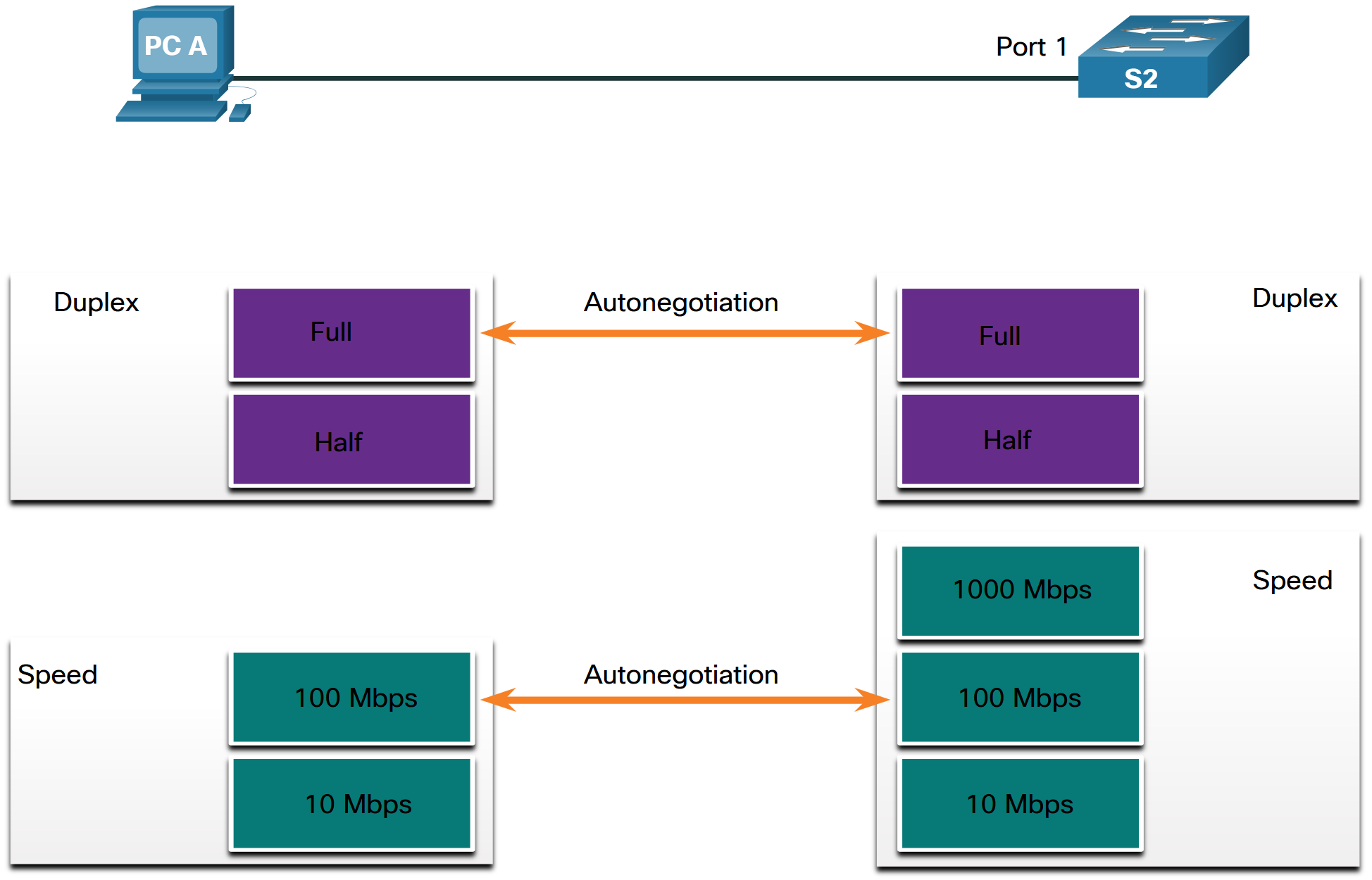
Duplex mismatch is one of the most common causes of performance issues on 10/100 Mbps Ethernet links. It occurs when one port on the link operates at half-duplex while the other port operates at full-duplex, as shown in the figure. Duplex mismatch occurs when one or both ports on a link are reset, and the autonegotiation process does not result in both link partners having the same configuration. It also can occur when users reconfigure one side of a link and forget to reconfigure the other. Both sides of a link should have autonegotiation on, or both sides should have it off. Best practice is to configure both Ethernet switch ports as full-duplex.
IPv4 Part 2
IPv4 Limitations
As we discussed previously, an IPv4 address is 32 bits long. This means that a maximum of 4.3 billion (2^32) devices can have a unique IP address. Since the world has over 8 billion inhabitants and per person we have more than one device that is connected to the internet it becomes clear that the address space does not suffice. IPv6 is designed to be the successor to IPv4. IPv6 has a larger 128-bit address space, providing 340 undecillion (i.e., 340 followed by 36 zeroes) possible addresses. However, IPv6 is more than just larger addresses. The depletion of IPv4 address space has been the motivating factor for moving to IPv6. As Africa, Asia and other areas of the world become more connected to the internet, there are not enough IPv4 addresses to accommodate this growth. As shown in the figure, all five RIRs have run out of IPv4 addresses. We will learn more about IPv6 in Lecture 10.
Public vs Private IPv4 Addresses
In the mid-1990s, with the introduction of the World Wide Web (WWW), private IPv4 addresses were introduced because of the depletion of IPv4 address space. Private IPv4 addresses are not unique and can be used internally within any network. Public IPv4 addresses are addresses which are globally routed between internet service provider (ISP) routers. However, not all available IPv4 addresses can be used on the internet. There are blocks of addresses called private addresses that are used by most organizations to assign IPv4 addresses to internal hosts.
The private address blocks are as follows:
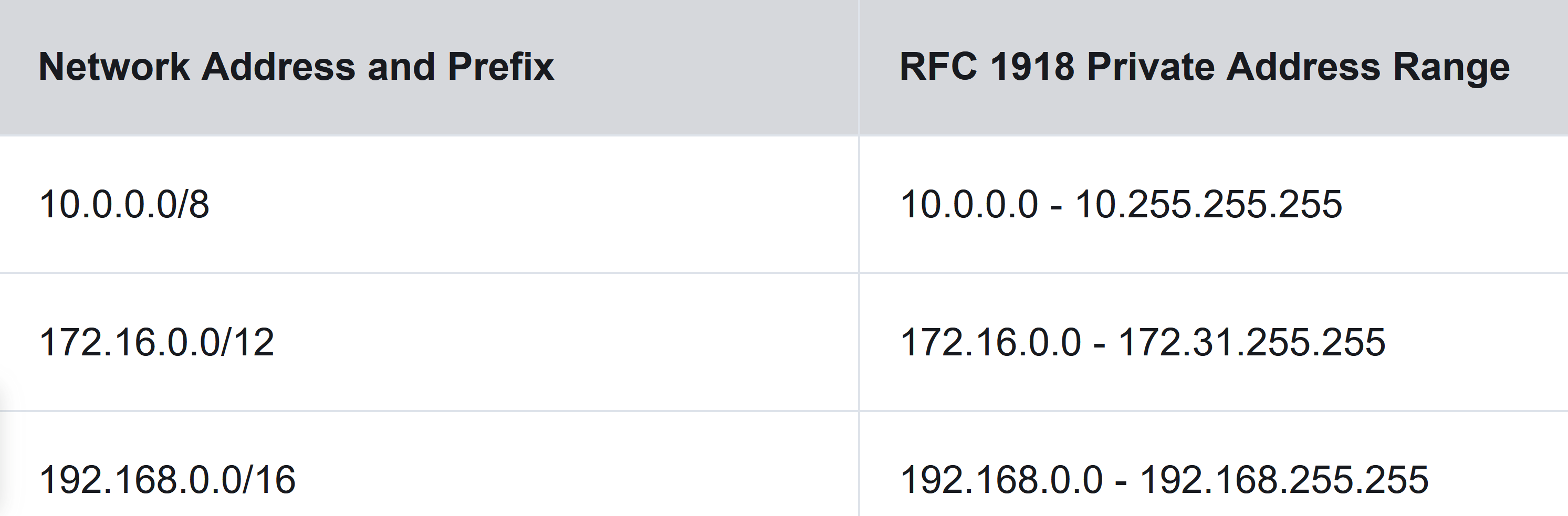
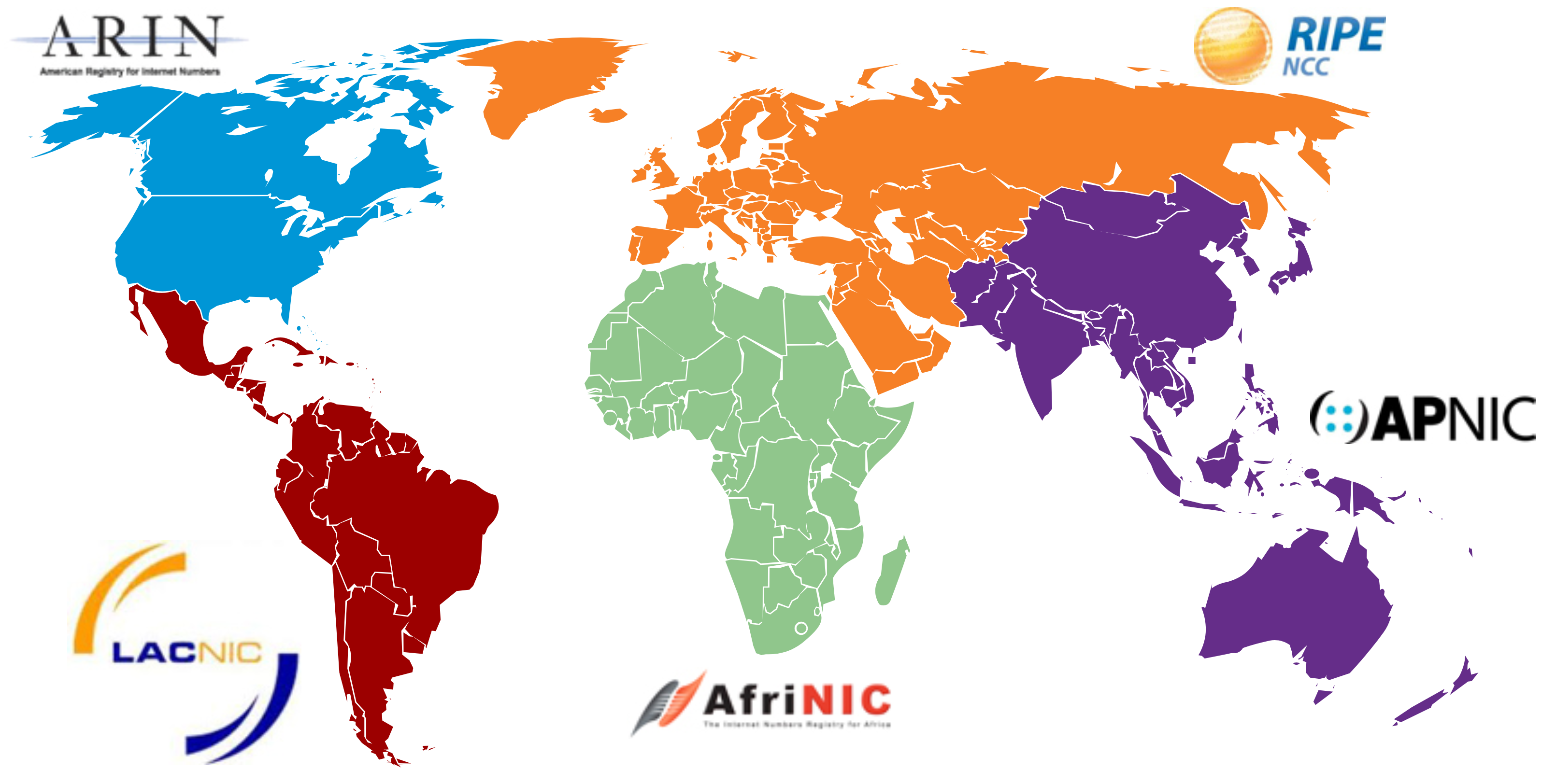
Public IPv4 addresses are addresses which are globally routed over the internet. Public IPv4 addresses must be unique. Both IPv4 and IPv6 addresses are managed by the Internet Assigned Numbers Authority (IANA). The IANA manages and allocates blocks of IP addresses to the Regional Internet Registries (RIRs). The five RIRs are shown in the figure. RIRs are responsible for allocating IP addresses to ISPs who provide IPv4 address blocks to organizations and smaller ISPs. Organizations can also get their addresses directly from an RIR (subject to the policies of that RIR). The RIRs are as follows:
- AfriNIC (African Network Information Centre) - Africa Region
- APNIC (Asia Pacific Network Information Centre) - Asia/Pacific Region
- ARIN (American Registry for Internet Numbers) - North America Region
- LACNIC (Regional Latin-American and Caribbean IP Address Registry) - Latin America and some Caribbean Islands
- RIPE NCC (Réseaux IP Européens Network Coordination Centre) - Europe, the Middle East, and Central Asia
NAT
Most internal networks, from large enterprises to home networks, use private IPv4 addresses for addressing all internal devices (intranet) including hosts and routers. However, private addresses are not globally routable. Before the ISP can forward this packet, it must translate the source IPv4 address, which is a private address, to a public IPv4 address using Network Address Translation (NAT). NAT is used to translate between private IPv4 and public IPv4 addresses. This is usually done on the router that connects the internal network to the ISP network. Private IPv4 addresses in the organization’s intranet will be translated to public IPv4 addresses before routing to the internet. Note: Although, a device with a private IPv4 address is not directly accessible from another device across the internet, the IETF does not consider private IPv4 addresses or NAT as effective security measures.
Organizations that have resources available to the internet, such as a web server, will also have devices that have public IPv4 addresses. As shown in the figure, this part of the network is known as the DMZ (demilitarized zone). The router in the figure not only performs routing, it also performs NAT and acts as a firewall for security.

Packets passing from the private network to the public network will have their source address modified, while packets passing from the public network back to the private network will have their destination address modified. To avoid ambiguity in how replies are translated, further modifications to the packets are required. For instance, assume a host is initiating a web page request from a web server. When the host initiates the web page request, the source port number is dynamically generated by the host to uniquely identify the conversation. Each request generated by a host will use a different dynamically created source port number. This process allows multiple conversations to occur simultaneously. For these protocols, the port numbers are changed so that the combination of IP address (within the IP header) and port number (within the Transport Layer header) on the returned packet can be unambiguously mapped to the corresponding private network destination.
DHCP
The Dynamic Host Configuration Protocol (DHCP) for IPv4 service automates the assignment of IPv4 addresses, subnet masks, gateways, and other IPv4 networking parameters. This is referred to as dynamic addressing. The alternative to dynamic addressing is static addressing. When using static addressing, the network administrator manually enters IP address information on hosts. Many networks use both DHCP and static addressing. DHCP is used for general purpose hosts, such as end user devices. Static addressing is used for network devices, such as gateway routers, switches, servers, and printers.
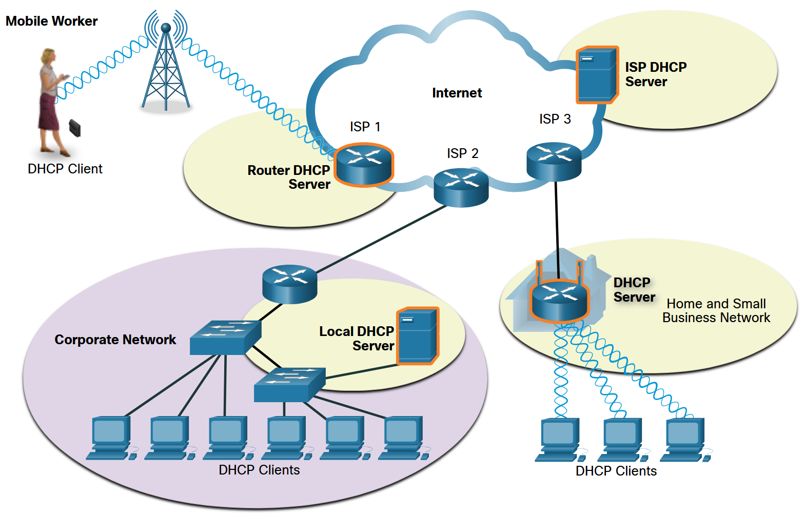
When a host connects to the network, the DHCP server is contacted, and an address is requested. The DHCP server chooses an address from a configured range of addresses called a pool and assigns (leases) it to the host. On larger networks, or where the user population changes frequently, DHCP is preferred for address assignment. New users may arrive and need connections; others may have new computers that must be connected. Rather than use static addressing for each connection, it is more efficient to have IPv4 addresses assigned automatically using DHCP. DHCP can allocate IP addresses for a configurable period of time, called a lease period. The lease period is an important DHCP setting, When the lease period expires or the DHCP server gets a DHCPRELEASE message the address is returned to the DHCP pool for reuse. Users can freely move from location to location and easily re-establish network connections through DHCP.
As the figure shows, various types of devices can be DHCP servers. The DHCP server in most medium-to-large networks is usually a local, dedicated PC-based server. With home networks, the DHCP server is usually located on the local router that connects the home network to the ISP.
DNS
In data networks, devices are labeled with numeric IP addresses to send and receive data over networks. Domain names were created to convert the numeric address into a simple, recognizable name. On the internet, fully-qualified domain names (FQDNs), such as http://www.cisco.com, are much easier for people to remember than 198.133.219.25, which is the actual numeric address for this server. If Cisco decides to change the numeric address of www.cisco.com, it is transparent to the user because the domain name remains the same. The new address is simply linked to the existing domain name and connectivity is maintained.
When a client makes a query, the server DNS process first looks at its own records to resolve the name. If it is unable to resolve the name by using its stored records, it contacts other servers to resolve the name. After a match is found and returned to the original requesting server, the server temporarily stores the numbered address in the event that the same name is requested again. The DNS cient service on Windows PCs also stores previously resolved names in memory. The ipconfig /displaydns command displays all of the cached DNS entries.
References
If you want to learn more about these topics you can check out Module 9, 11, 14.4, 15.4 in the netacad course (CCNA: Introduction to Networks).
Exercises
- 11.10.1 Design and Implement a VLSM Addressing Scheme