IP Address Part 1
The use of IP addresses is the primary means of enabling devices to locate one another and establish end-to-end communication on the internet. Each end device on a network must be configured with an IP address. Examples of end devices include these:
- Computers (work stations, laptops, file servers, web servers)
- Network printers
- VoIP phones
- Security cameras
- Smart phones
- Mobile handheld devices (such as wireless barcode scanners)
IP Address Structure
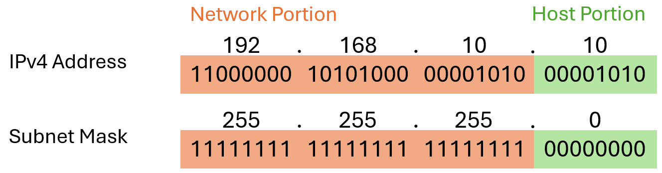
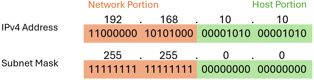
There are two different IP protocols currently being used: IPv4 and IPv6. For now we will focus on IPv4. More information about how IPv6 exists and how it is different will follow in Lecture 5. An IPv4 address is a 32-bit hierarchical address that is made up of a network portion and a host portion. IPv4 addresses are generally displayed by four decimal numbers between 0 and 255 spereated by dots, also known as a dotted decimal notation. IPv4 addresses are assigned to individual devices connected to a network. The bits within the network portion of the address must be identical for all devices that reside in the same network. The bits within the host portion of the address must be unique to identify a specific host within a network. If two hosts have the same bit-pattern in the specified network portion of the 32-bit stream, those two hosts will reside in the same network.
Subnetmask
The IPv4 subnet mask is used to differentiate the network portion from the host portion of an IPv4 address. When an IPv4 address is assigned to a device, the subnet mask is used to determine the network address of the device. The network address represents all the devices on the same network. Note that the subnet mask does not actually contain the network or host portion of an IPv4 address, it just tells the computer where to look for the part of the IPv4 address that is the network portion and which part is the host portion. Similar to the IPv4 address the subnet mask is also often displayed in dotted decimal notation which represents a 32-bit value.
The Prefix Length
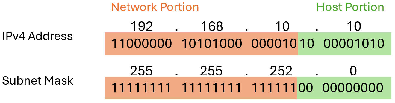
Expressing network addresses and host addresses with the dotted decimal subnet mask address can become cumbersome. Fortunately, there is an alternative method of identifying a subnet mask, a method called the prefix length. The prefix length is the number of bits set to 1 in the subnet mask. It is written in “slash notation”, which is noted by a forward slash (/) followed by the number of bits set to 1. Therefore, count the number of bits in the subnet mask and prepend it with a slash. Here are some examples using the IPv4 address 192.168.10.10:
| Subnetmask | Bit representation | Prefix Length | Slash Notation |
|---|---|---|---|
| 255.255.0.0 | 11111111.11111111.00000000.00000000 |
/16 | 192.168.10.10/16 |
| 255.255.252.0 | 11111111.11111111.11111100.00000000 |
/22 | 192.168.10.10/22 |
| 255.255.255.0 | 11111111.11111111.11111111.00000000 |
/24 | 192.168.10.10/24 |
| 255.255.255.224 | 11111111.11111111.11111111.11100000 |
/27 | 192.168.10.10/27 |
Logic AND
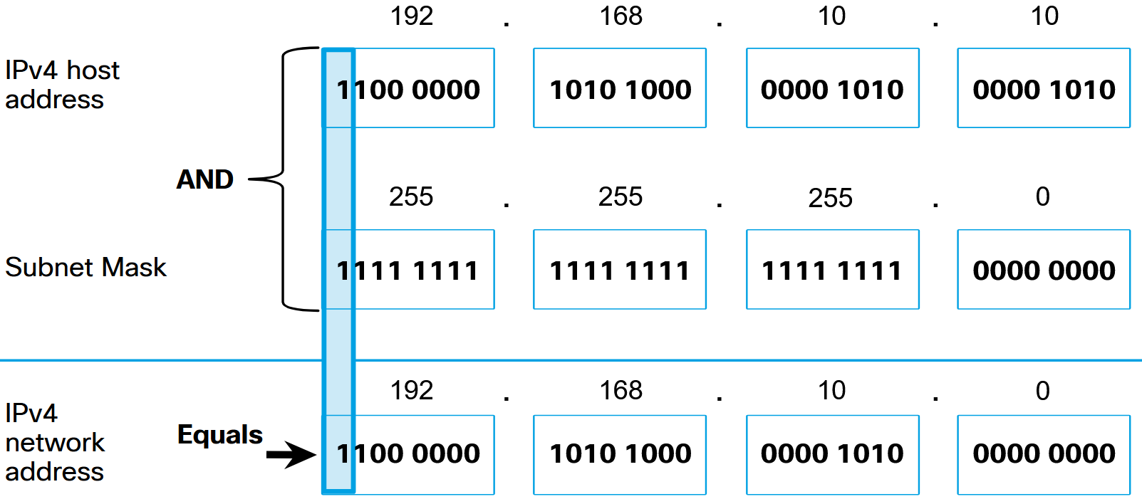
The actual process used to identify the network portion and host portion is called ANDing. A logic AND is one of the Boolean operation used in digital logic. Logical AND is the comparison of two bits that produce the results shown below. Note how only a 1 AND 1 produces a 1. Any other combination results in a 0.
- 1 AND 1 = 1
- 1 AND 0 = 0
- 0 AND 1 = 0
- 0 AND 0 = 0
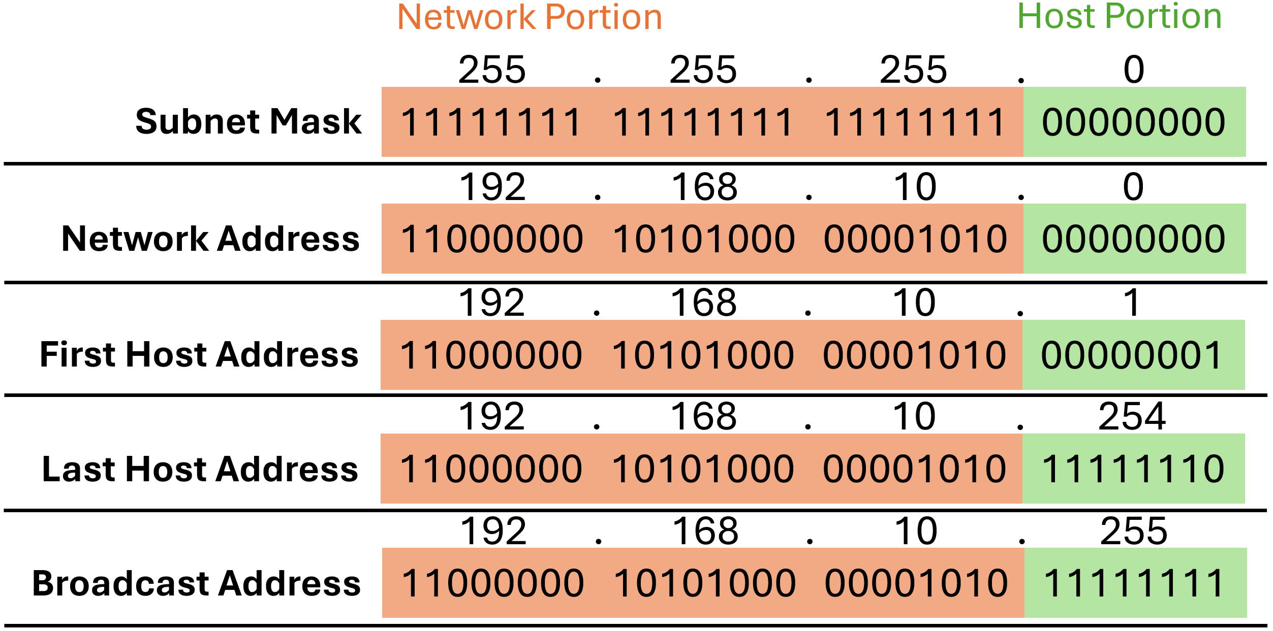
To identify the network address of an IPv4 host, the IPv4 address is logically ANDed, bit by bit, with the subnet mask. ANDing between the address and the subnet mask yields the network address:
Important Addresses
Within each network are three types of IP addresses:
- Network address: A network address is an address that represents a specific network. A host determines its network address by performing an AND operation between its IPv4 address and its subnet mask.
- Host addresses: Host addresses are addresses that can be assigned to a device. The host portion of the address is the bits indicated by 0 bits in the subnet mask. Host addresses can have any combination of bits in the host portion except for all 0 bits (this would be a network address) or all 1 bits (this would be a broadcast address).
- Broadcast address: A broadcast address is an address that is used when it is required to reach all devices on the IPv4 network. As shown in the table, the network broadcast address has all 1 bits in the host portion, as determined by the subnet mask.
Unicast, Broadcast and Multicast
There are different ways to send a packet from a source device, and these different transmissions affect the destination IPv4 addresses:
- Unicast: Unicast transmission refers to one device sending a message to one other device in one-to-one communications. A unicast packet has a destination IP address that is a unicast address which goes to a single recipient. A source IP address can only be a unicast address, because the packet can only originate from a single source. This is regardless of whether the destination IP address is a unicast, broadcast or multicast.
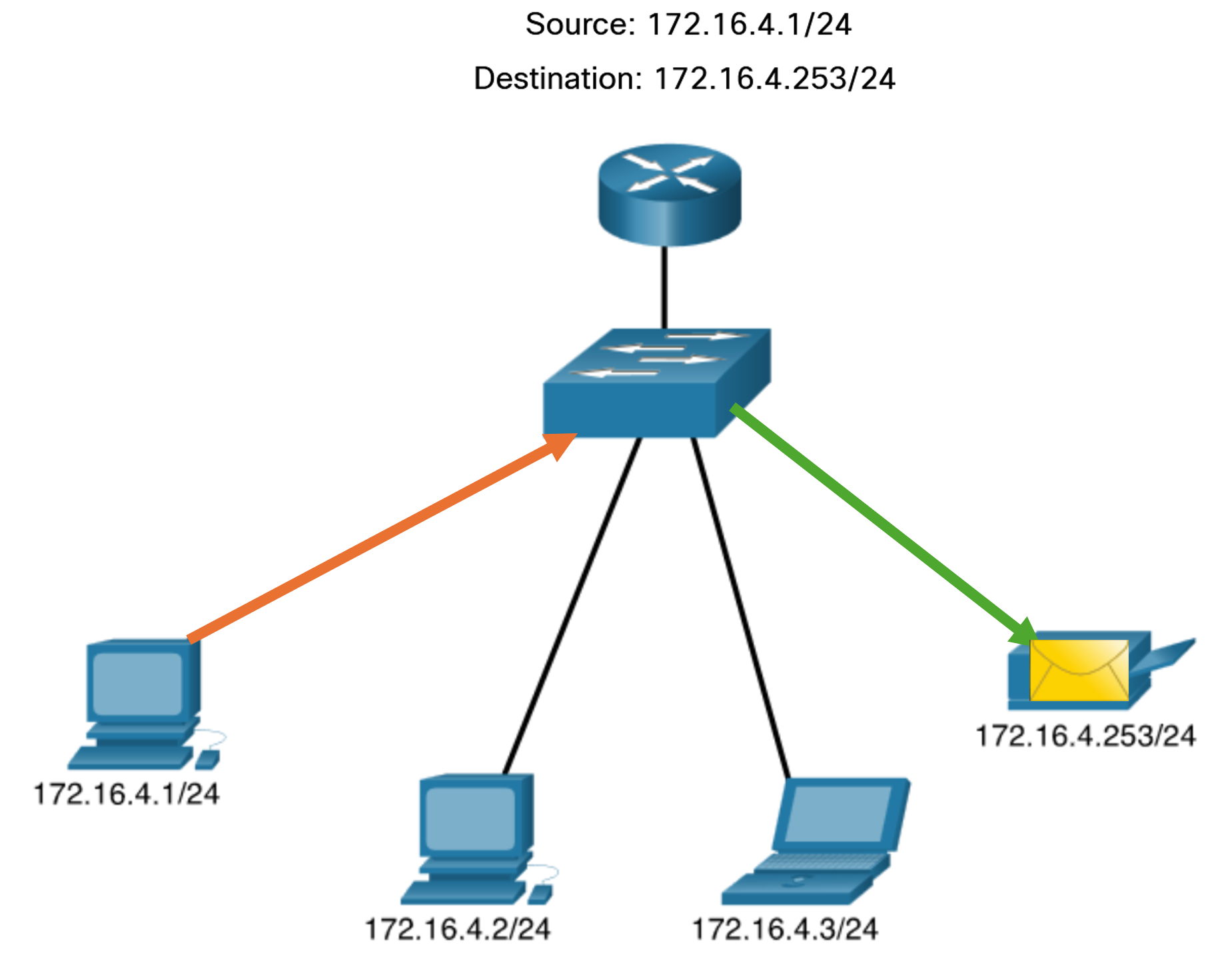
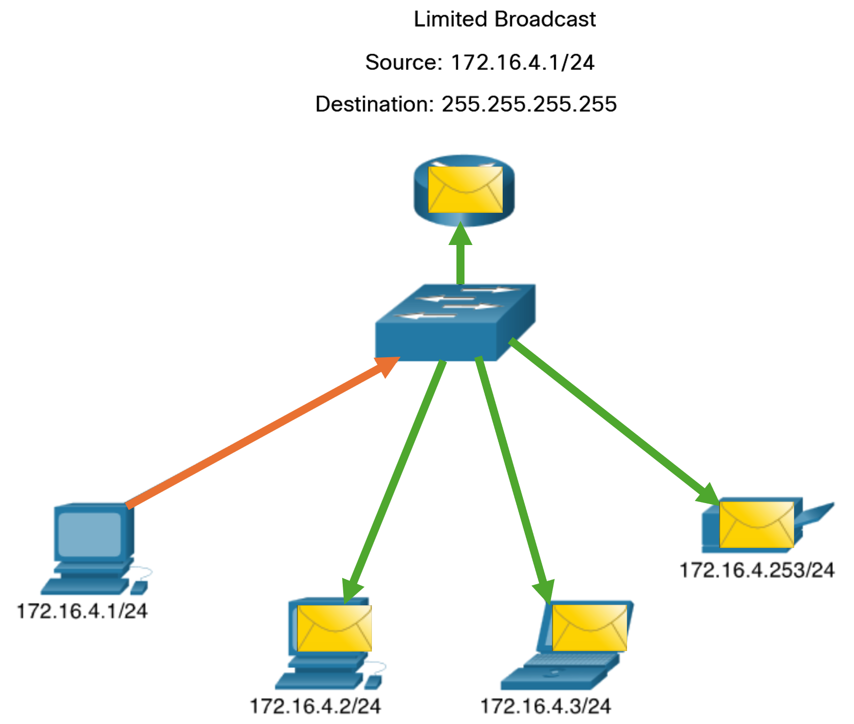
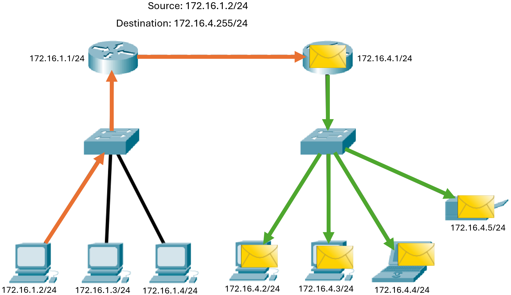
- Broadcast: Broadcast transmission refers to a device sending a message to all the devices on a network in one-to-all communications. A broadcast packet has a destination IP address with all ones (1s) in the host portion, or 32 one (1) bits. A broadcast packet must be processed by all devices in the same broadcast domain. A broadcast domain identifies all hosts on the same network segment. A broadcast may be directed or limited. A directed broadcast is sent to all hosts on a specific network. For example, a host on the 172.16.4.0/24 network sends a packet to 172.16.4.255. A limited broadcast is sent to 255.255.255.255. By default, routers do not forward broadcasts. Broadcast packets use resources on the network and make every receiving host on the network process the packet. Therefore, broadcast traffic should be limited so that it does not adversely affect the performance of the network or devices. Because routers separate broadcast domains, subdividing networks can improve network performance by eliminating excessive broadcast traffic.
-
IP Directed Broadcast: In addition to the 255.255.255.255 broadcast address, there is a broadcast IPv4 address for each network. Called a directed broadcast, this address uses the highest address in the network, which is the address where all the host bits are 1s. For example, the directed broadcast address for 192.168.1.0/24 is 192.168.1.255. This address allows communication to all the hosts in that network. To send data to all the hosts in a network, a host can send a single packet that is addressed to the broadcast address of the network. A device that is not directly connected to the destination network forwards an IP directed broadcast in the same way it would forward unicast IP packets destined to a host on that network. When a directed broadcast packet reaches a router that is directly connected to the destination network, that packet is broadcast on the destination network. Because of security concerns and prior abuse from malicious users, directed broadcasts are turned off by default starting with Cisco IOS Release 12.0 with the global configuration command
no ip directed-broadcasts.
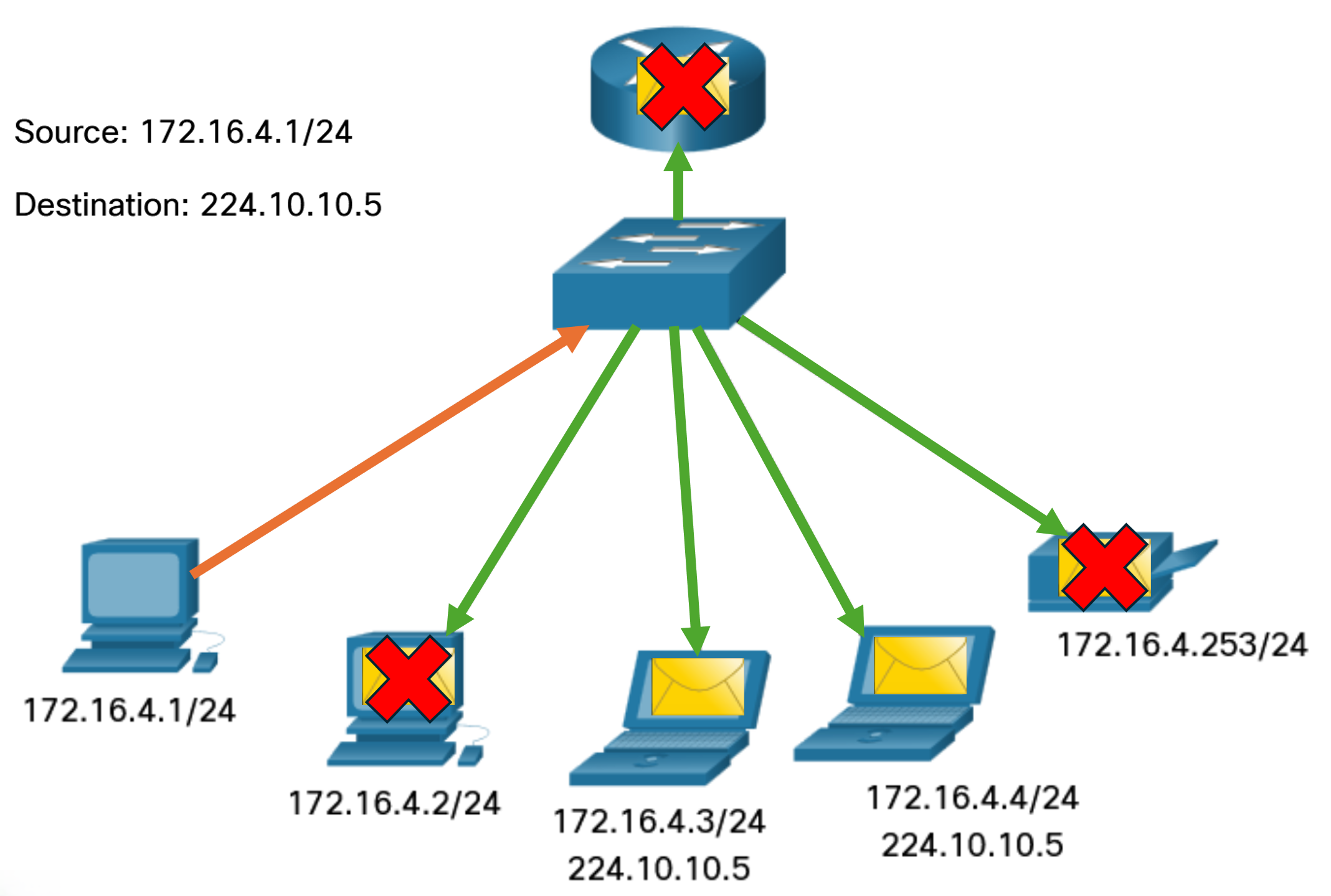
- Multicast: Multicast transmission reduces traffic by allowing a host to send a single packet to a selected set of hosts that subscribe to a multicast group. A multicast packet is a packet with a destination IP address that is a multicast address. IPv4 has reserved the 224.0.0.0 to 239.255.255.255 addresses as a multicast range. Hosts that receive particular multicast packets are called multicast clients. The multicast clients use services requested by a client program to subscribe to the multicast group. Each multicast group is represented by a single IPv4 multicast destination address. When an IPv4 host subscribes to a multicast group, the host processes packets addressed to this multicast address, and packets addressed to its uniquely allocated unicast address.
Network Segmentation
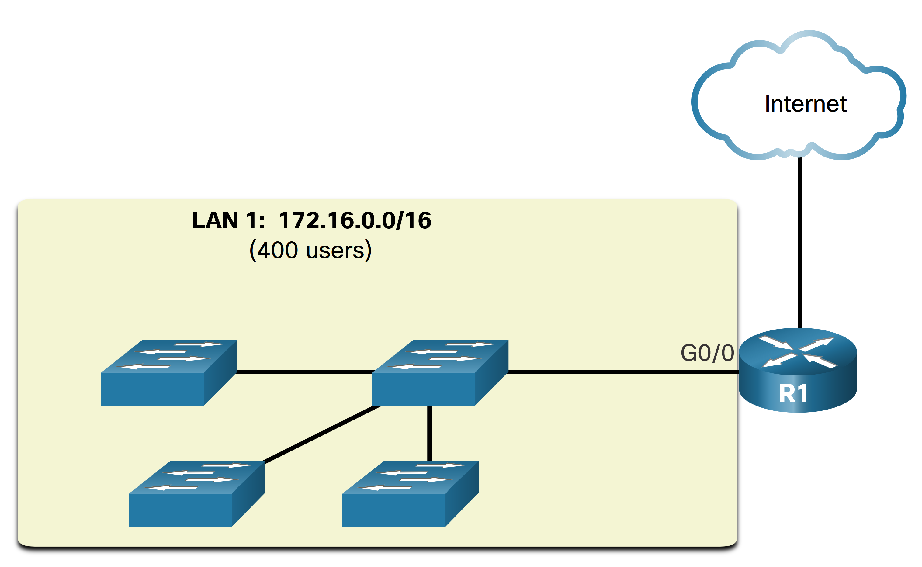
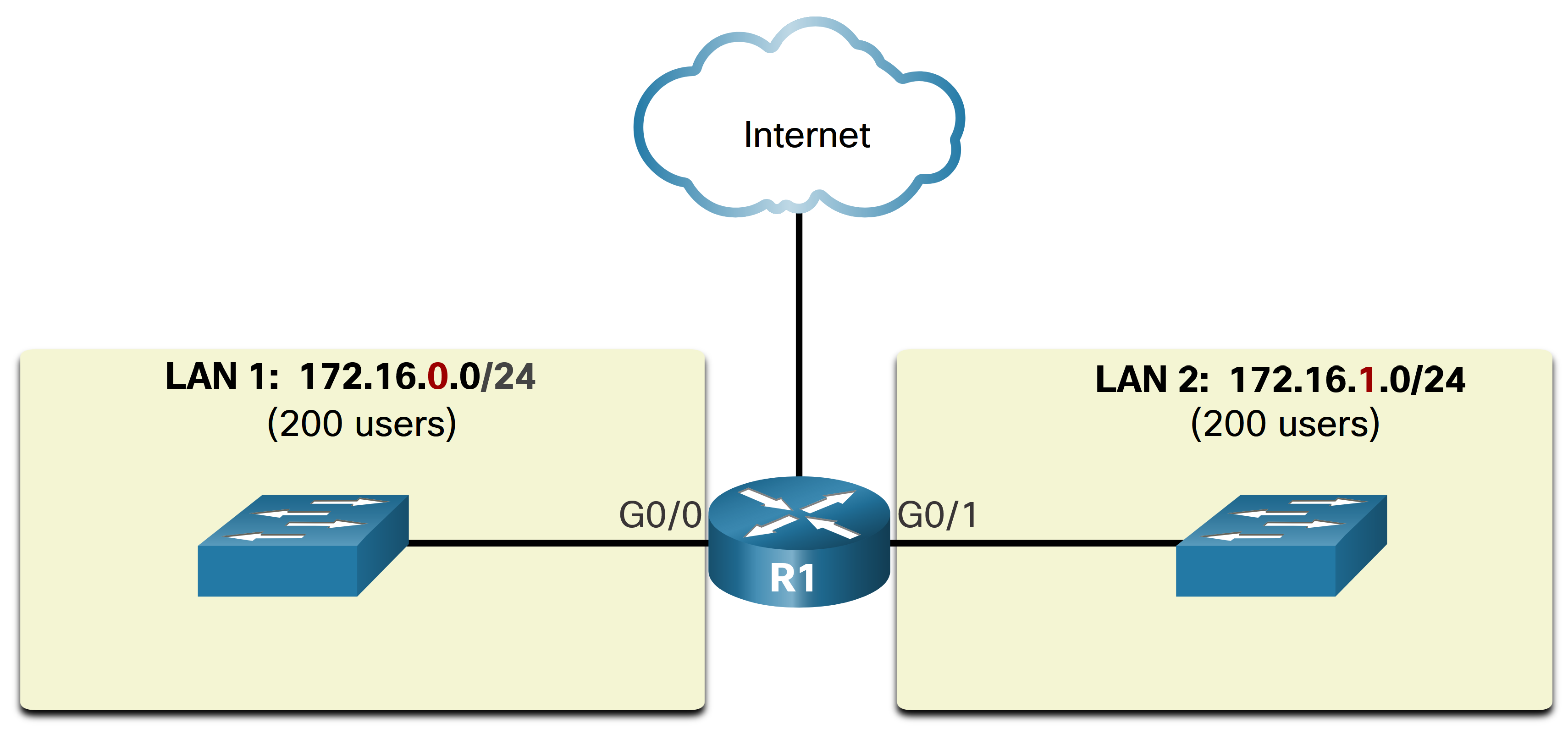
As previously mentioned one type of message is a broadcast message, which is sent from one source to all devices on a given network. These messages use up a lot of resources of the network and scale poorly with an increasing amount of end devices. In an Ethernet LAN, devices use broadcasts and the Address Resolution Protocol (ARP) to locate other devices. ARP sends Layer 2 broadcasts to a known IPv4 address on the local network to discover the associated MAC address. Devices on Ethernet LANs also locate other devices using services. A host typically acquires its IPv4 address configuration using the Dynamic Host Configuration Protocol (DHCP) which sends broadcasts on the local network to locate a DHCP server. Large broadcast domains can therefore result in slow network operations due to the significant amount of traffic it can cause, and slow device operations because a device must accept and process each broadcast packet. The solution is to reduce the size of the network to create smaller broadcast domains in a process called subnetting. These smaller network spaces are called subnets. In the figure, the 400 users in LAN 1 with network address 172.16.0.0 /16 have been divided into two subnets of 200 users each: 172.16.0.0 /24 and 172.16.1.0 /24. Broadcasts are only propagated within the smaller broadcast domains. Therefore, a broadcast in LAN 1 would not propagate to LAN 2. Notice how the prefix length has changed from a single /16 network to two /24 networks. This is the basis of subnetting: using host bits to create additional subnets.
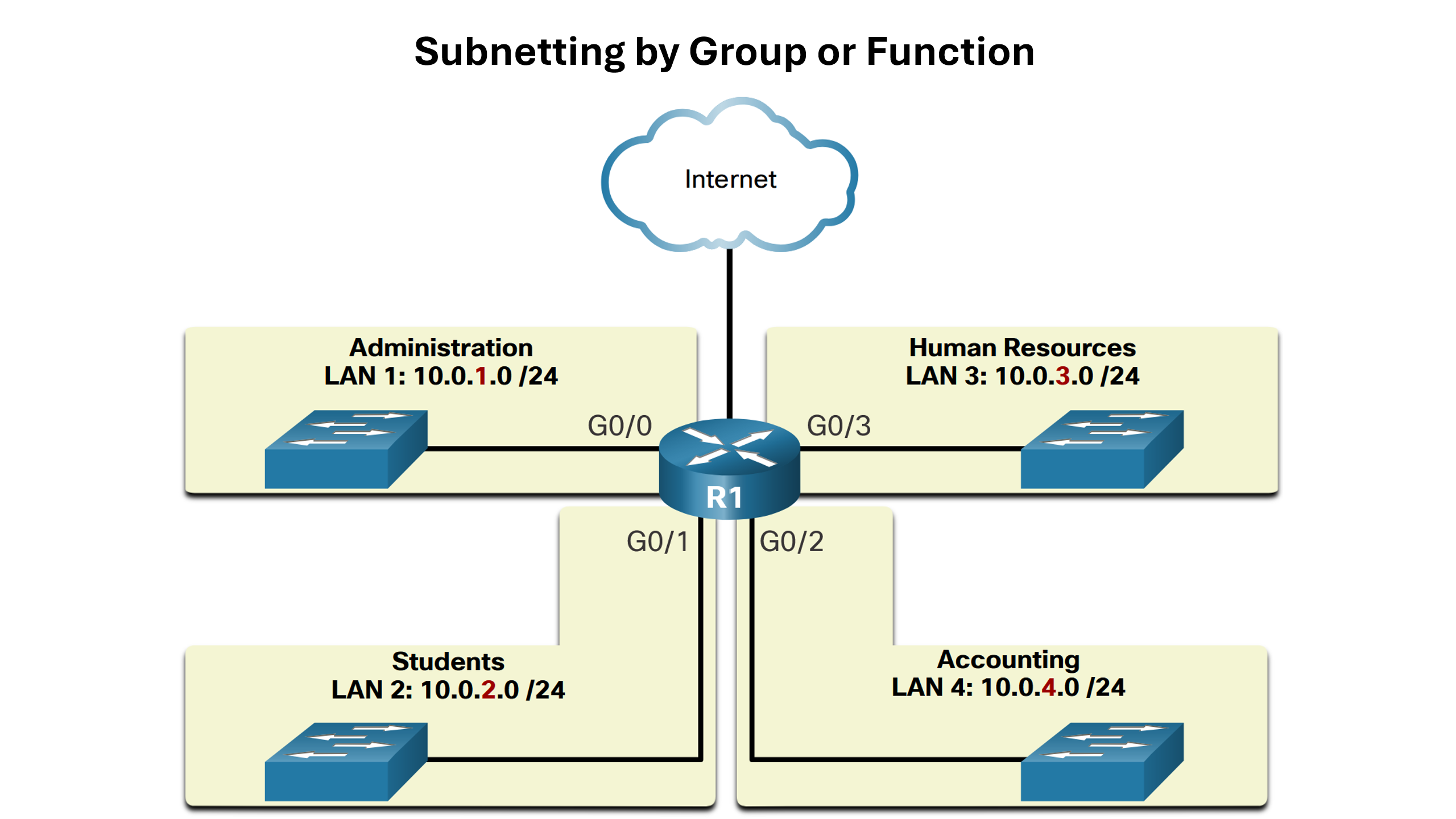
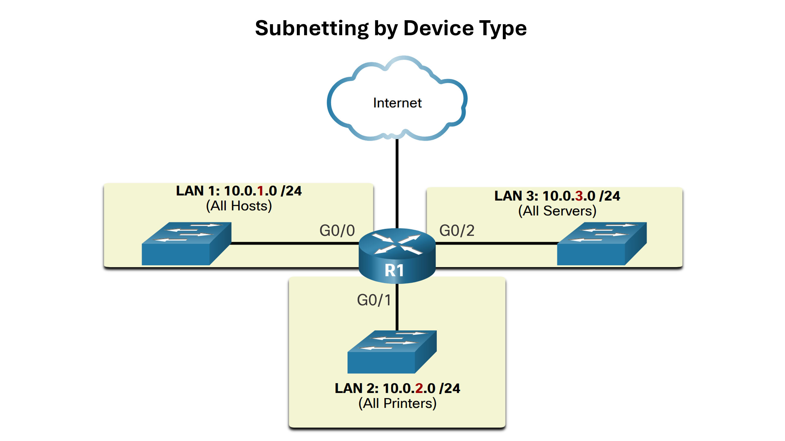
Subnetting reduces overall network traffic and improves network performance. It also enables an administrator to implement security policies such as which subnets are allowed or not allowed to communicate together. Another reason is that it reduces the number of devices affected by abnormal broadcast traffic due to misconfigurations, hardware/software problems, or malicious intent. The subnetting policy will vary from network to network but here are a view examples:
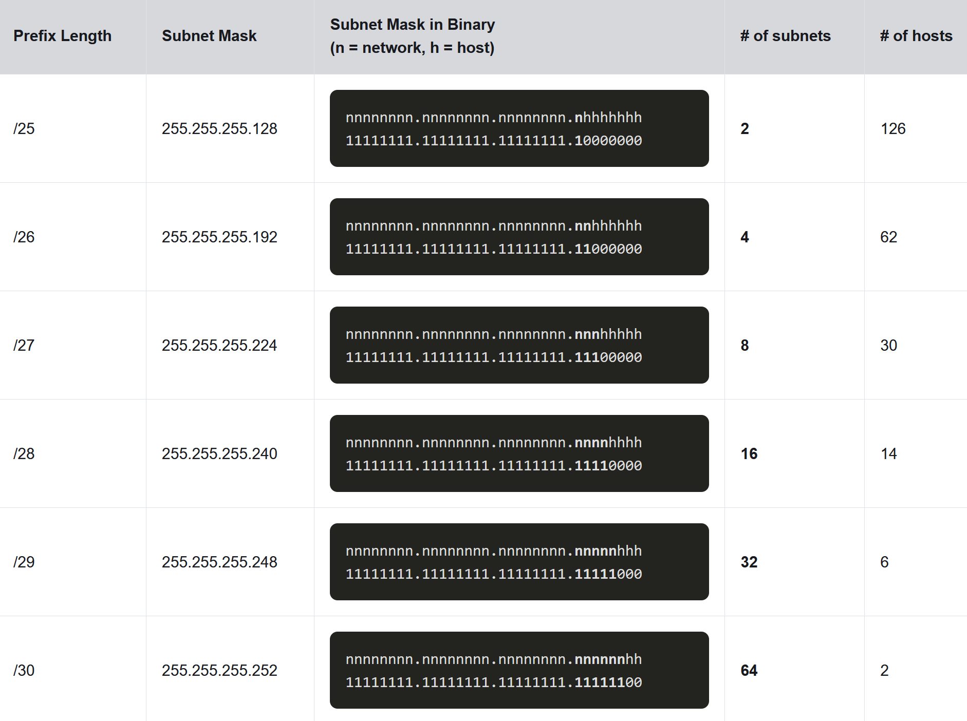
Subnet an IPv4 Network
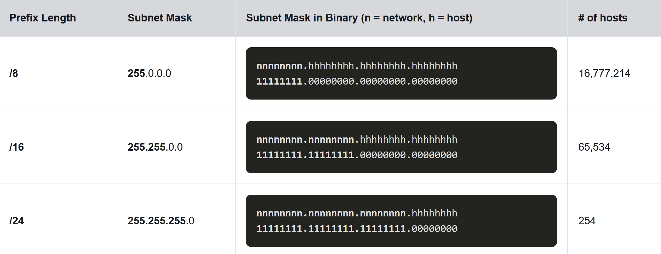
IPv4 subnets are created by using one or more of the host bits as network bits. This is done by extending the subnet mask to borrow some of the bits from the host portion of the address to create additional network bits. The more host bits that are borrowed, the more subnets that can be defined. The more bits that are borrowed to increase the number of subnets reduces the number of hosts per subnet. Networks are most easily subnetted at the octet boundary of /8, /16, and /24. The table identifies these prefix lengths. Notice that using longer prefix lengths decreases the number of hosts per subnet.
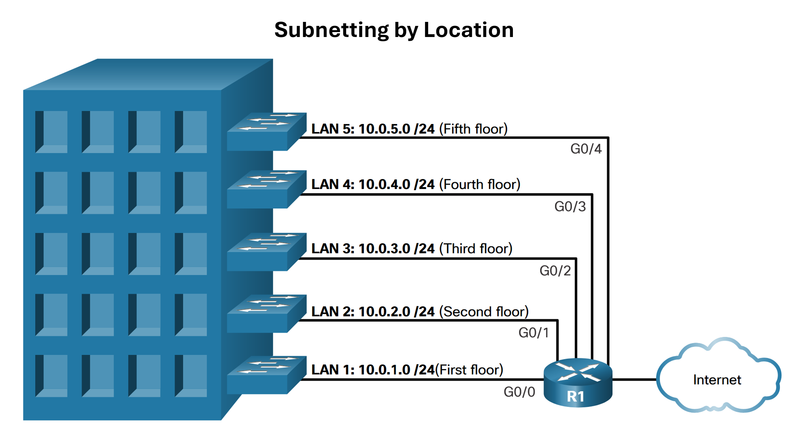
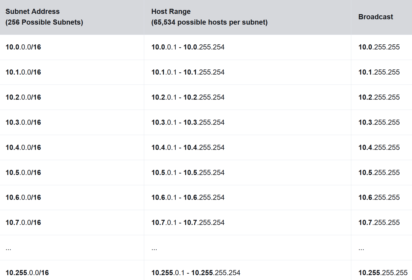
To understand how subnetting on the octet boundary can be useful, consider the following example. Assume an enterprise has chosen the private address 10.0.0.0/8 as its internal network address. That network address can connect 16,777,214 hosts in one broadcast domain. Obviously, having more than 16 million hosts on a single subnet is not ideal. The enterprise could further subnet the 10.0.0.0/8 address at the octet boundary of /16 as shown in the table. This would provide the enterprise the ability to define up to 256 subnets (i.e., 10.0.0.0/16 - 10.255.0.0/16) with each subnet capable of connecting 65,534 hosts. Notice how the first two octets identify the network portion of the address whereas the last two octets are for host IP addresses.
The examples shown thus far borrowed host bits from the common /8, /16, and /24 network prefixes. However, subnets can borrow bits from any host bit position to create other masks. For instance, a /24 network address is commonly subnetted using longer prefix lengths by borrowing bits from the fourth octet. This provides the administrator with additional flexibility when assigning network addresses to a smaller number of end devices.
Subnet with the Magic Number
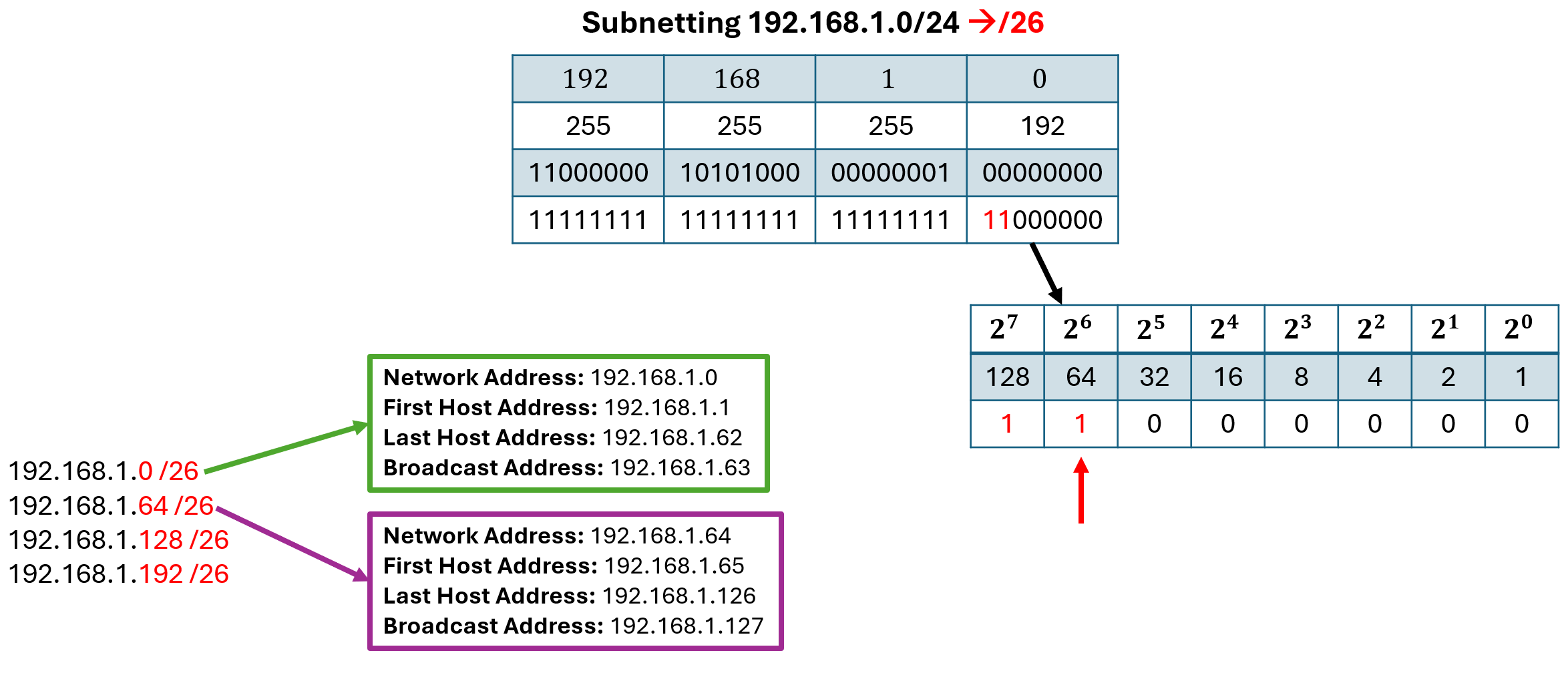
One method to find the sub-networks easily and quickly is using the magic number trick. Lets use the following example: we are given the network address 192.168.1.0/24 and are supposed to subnett it into /26 networks. As we can see in the figure below, when changing the network to /26 we have to borrow 2 bits from the last octet (last 8 bits) of the address. To calculate the network addresses of our subnetted network we look at the lowest bit in the subnet mask that is a one and check in which octet it’s located. We than calculate the decimal value of that bit within that octet. In our example the last 1 is in the fourth octet and represents a 64 as a decimal value. This is our magic number. The first network address is 192.168.1.0/26. The next network address is the previous one plus 64 in the fourth octet: 192.168.1.64/26. This process of adding the magic number to the previous network address continues until we would surpass 255 resulting in four subnetworks:
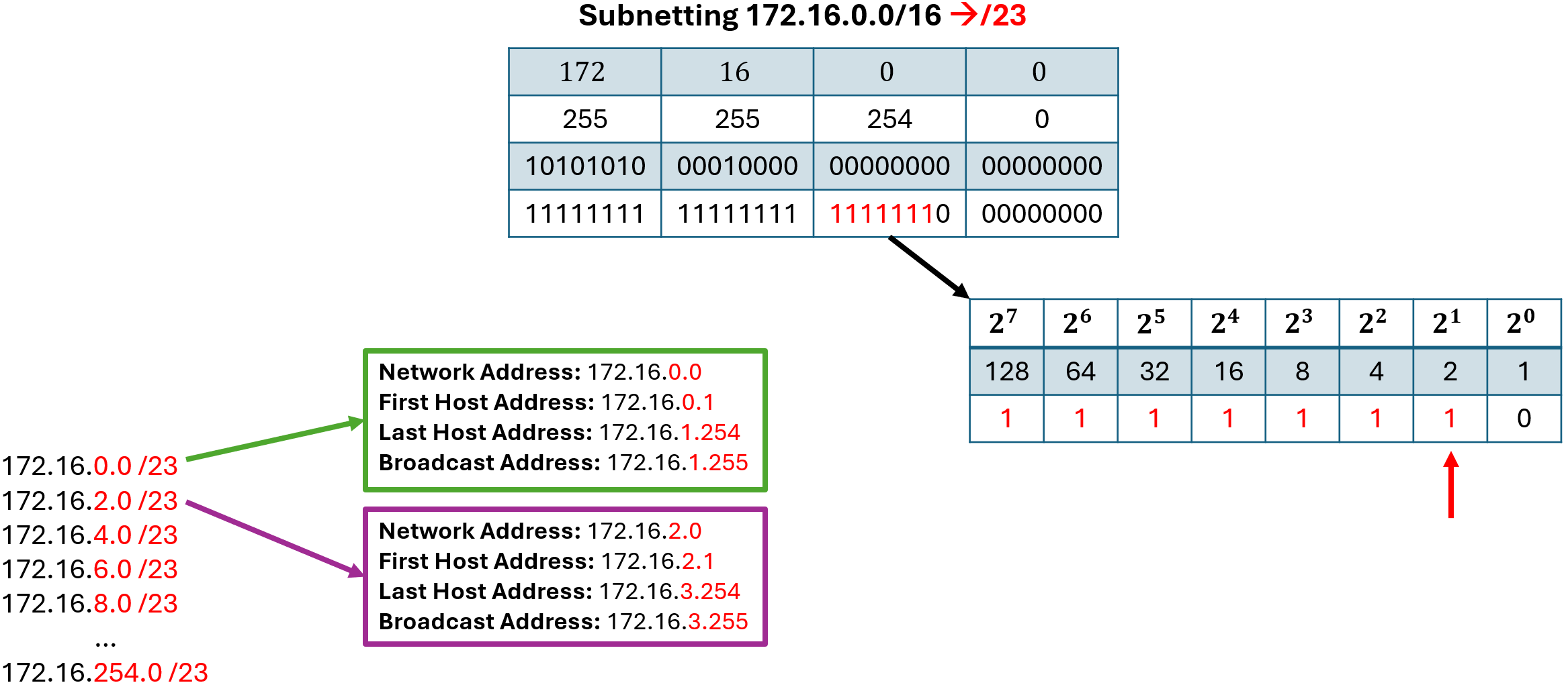
In the previous example we borrowed bits from the last octet of the address. Let us now look at how the magic number calculations work if we borrow bits in a different octet. We are given the address 172.16.0.0/16 and should subnett it into /23 networks. This means that we have to borrow 7 bits from the third octet, as visualized in the following figure. In the new subnet mask the last 1 bit is in the third octet and represents the decimal value of 2. We can now use the magic number 2 by increasing the network address by 2 in the third octet:
- 172.16.0.0/23
- 172.16.2.0/23
- 172.16.4.0/23
- …
- 172.16.254.0/23
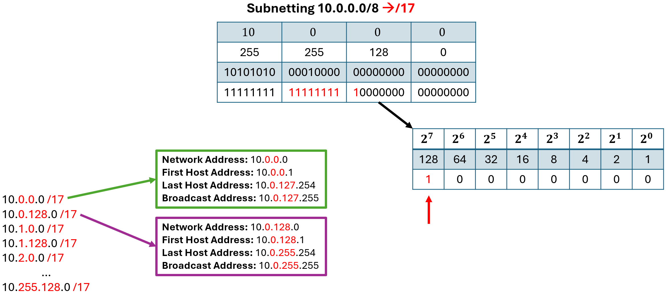
A more different example is if we have to borrow bits from more then one octet. Let us use the following example: we are given the network address 10.0.0.0/8 and are supposed to subnett it into /17networks. The process of finding the magic number is still the same: we look for the last 1 in the new subnet mask and calculate its decimal value within that octet. In our example the magic number is in the third octet and represent the value 128. But since we are borrowing bits not only from the third but also from the second octet we have to keep adding the magic number until also the second ocetet value would go aboth 255. So in this case we not only have the networks 10.0.0.0/17 and 10.0.128.0/17 but rather have the following:
- 10.0.0.0/17
- 10.0.128.0/17
- 10.1.0.0/17
- 10.1.128.0/17
- 10.2.0.0/17
- …
- 10.255.128.0/17
References
If you want to learn more about these topics you can check out Module 11 in the netacad course (CCNA: Introduction to Networks).
Exercises
- 11.6.6 Calculate IPv4 Subnets
- 11.5.5 Subnet an IPv4 Network